OpenWiFi
Overview
OpenWiFi (OW) is an OpenWRT-derived firmware that bundles drivers, the Linux OS, and Ucentral command and control software to create an IEEE Std 802.11 Wireless Access Point (WAP). The rXg uses components of Ucentral to discover, configure, monitor, and manage these WAPs.
Controller Types
There are two controller types available:
| Feature | WSS (Recommended) | SDK (Deprecated) |
|---|---|---|
| Architecture | rXg acts as controller directly | External OWGW VM |
| Deployment | Simple, no VM required | Requires virtualization |
| Resource Usage | Minimal | 8 GB RAM, 8 cores, 40 GB storage |
| Use Case | All new deployments | Legacy support only |
| Status | Active Development | Deprecated - No new features |
Important: The OpenWiFi SDK (OWGW) controller is deprecated and receives no new feature development. All new OpenWiFi deployments should use the WSS controller. Downstream port configuration and other advanced features are only available in WSS mode.
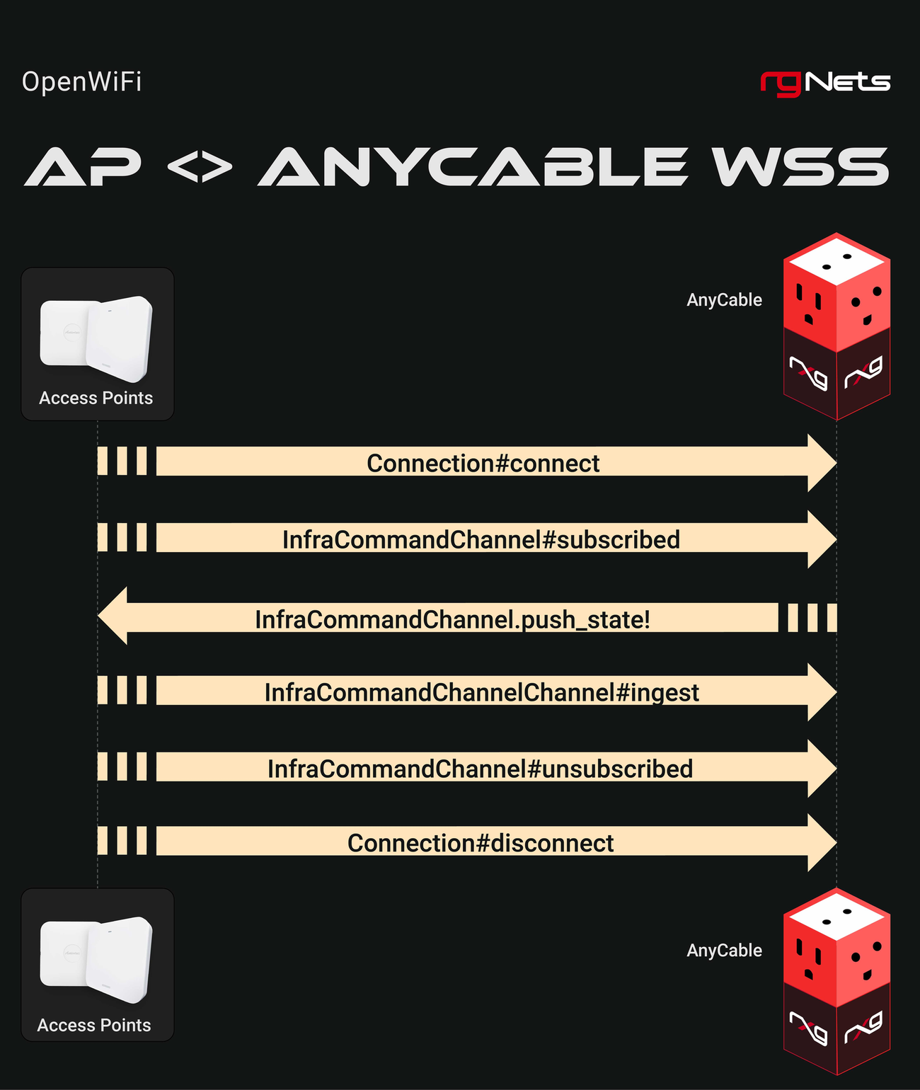
How It Works
The rXg interacts with OpenWiFi devices using a combination of Secure Shell (SSH) for initial setup and a persistent Websocket Secure (WSS) connection for ongoing management.
The adoption process consists of these parts:
- Installation of Correct Firmware onto Target WAP: The rXg includes built-in methods for using SSH to setup a target WAP with the proper firmware.
- C&C Acquisition: Once the WAP boots on the proper firmware, it discovers its Command and Control rXg through DHCP option 224. It downloads the latest available copy of the RG WSS Client from this rXg.
- Certificate Management: The RG WSS Client acquires a certificate for the WAP if necessary, via EST, with the rXg acting as the EST server.
- Persistent WSS Management: The WAP opens a persistent WSS connection to the rXg which is used for all further management of the WAP.
Once the WSS connection is active, it becomes the primary channel for all subsequent operations, including configuration updates and firmware management.
Installation
This section covers the installation and deployment of OpenWiFi controllers on the rXg. Both controller types use Config Template #7 for deployment, which can be found in System >> Backup >> Config Templates (click "Show Examples" to reveal example templates).
Prerequisites
Before installing either controller type, ensure the following requirements are met:
Network Requirements: - It is recommended that the rXg WAN uplink be on a public IP address or CGNAT address space (100.64.0.0/10). While WSS can function with a private WAN address as long as the rXg hostname resolves correctly and has a valid SSL certificate, a public or CGNAT address simplifies certificate validation and WAP connectivity. - The rXg hostname must be resolvable by WAPs and must match the SSL certificate installed on the rXg - WAPs must be able to reach the rXg on HTTPS (port 443) - DHCP must be configured to provide Option 224 for WAP controller discovery (part of Template 7 for automated creation)
Certificate Requirements:
- A valid SSL certificate must be installed on the rXg before beginning WSS setup. WAPs validate the rXg certificate during the WSS handshake, and self-signed or expired certificates will prevent successful connections.
- A Local Certificate Authority (CA) must be created on the rXg (part of Template 7 for automated creation)
- The CA Common Name (CN) must match the rXg hostname
- The CA should have a long lifespan (recommended: 10 years / 3650 days)
Software Requirements: - The rXg must be running code version 16.247 or newer for WSS support. On code version 16.246 or older, WSS functionality is not available. It is recommended to update to the latest code when possible to get access to WSS features. - After upgrading the rXg to a new code version, navigate to System >> Backup >> Config Templates, delete all existing example templates, and click the Create Defaults button to regenerate them. This ensures that the templates are up to date and include the latest WSS configuration options.
WSS Installation (Recommended)
The WSS controller is the recommended deployment method. The rXg acts as the OpenWiFi controller directly, communicating with WAPs via secure WebSocket connections. This approach requires no external VM and is simpler to deploy and maintain.
Step 1: Apply Config Template #7
- Navigate to System >> Backup >> Config Templates
- Click Show Examples to reveal example templates
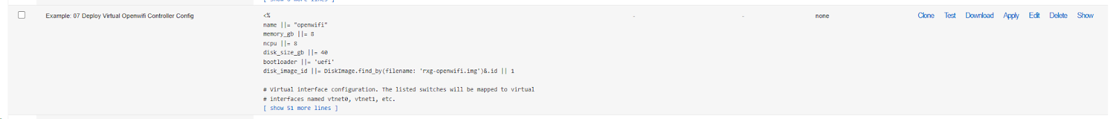
- Locate Example: 07 Deploy Virtual Openwifi Controller
- Verify the
infdev_devicevariable is set toopenwifi_wss(this is the default) - Optionally customize the CA parameters:
ca_country ||= 'US'
ca_state ||= 'California'
ca_locale ||= 'San Francisco'
ca_common_name ||= DeviceOption.active.domain_name
ca_email_address ||= "certs@#{DeviceOption.active.domain_name}"
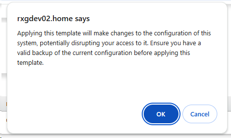
- Click Apply and confirm the deployment
The template automatically creates: - A Local Certificate Authority for WAP authentication - An EST Server Option for certificate enrollment - A WLAN Controller configured for WSS mode (host: 127.0.0.1) - A default Access Point Zone and Profile - DHCP Option 224 for WAP controller discovery
Step 2: Configure WSS Client Access Control
After applying the template, you must configure WSS Client Access Policies or WSS Client Access WAN Targets on the wireless device. The controller will not show as Online until at least one of these is configured.
- Navigate to Network >> Wireless >> WLAN Controllers
- Edit the OpenWiFi WSS wireless device
- Configure at least one of the following:
- WSS Client Access Policies: Select the LAN policies that should be allowed to download the WSS client. Use this when WAPs are on a managed LAN segment with an assigned policy.
- WSS Client Access WAN Targets: Select the WAN targets that define the IP ranges from which WSS client downloads are permitted. Use this when WAPs connect from WAN-side addresses.
- Click Update
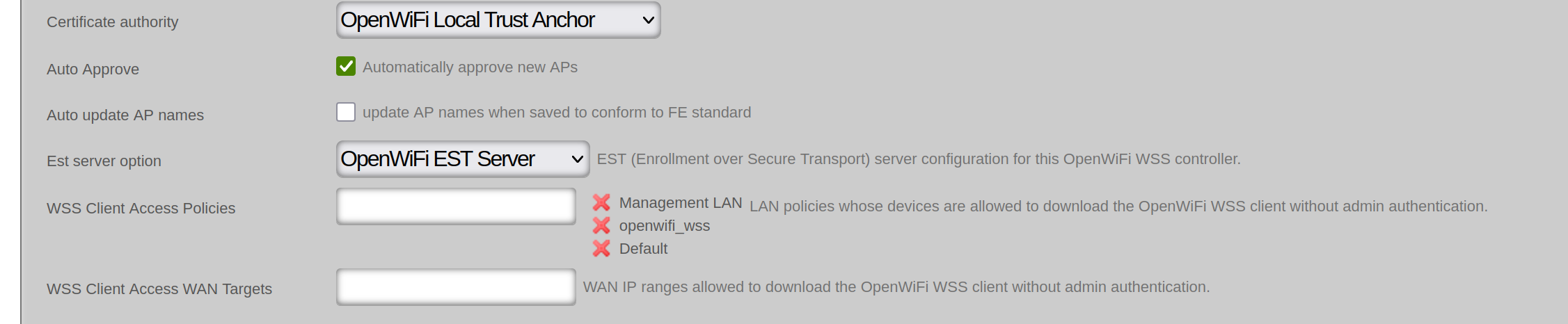
Note: This is a security requirement. The system uses a fail-closed model where WAPs cannot download the WSS client package until access control is explicitly configured. If neither policies nor WAN targets are set, the controller will display as Offline with a warning icon.
Step 3: Verify Post-Template Configuration
After applying the template, verify that the following records were created correctly:
EST Server: 1. Navigate to Services >> Servers >> EST Server Options 2. Confirm that an EST Server Option named OpenWiFi EST Server exists and is active 3. Verify that the EST Server Option has appropriate policies or WAN targets associated with it to allow certificate enrollment from your WAPs. In a most common scenario, it is sufficient to use the OpenWiFi related infrastructure device as shown below

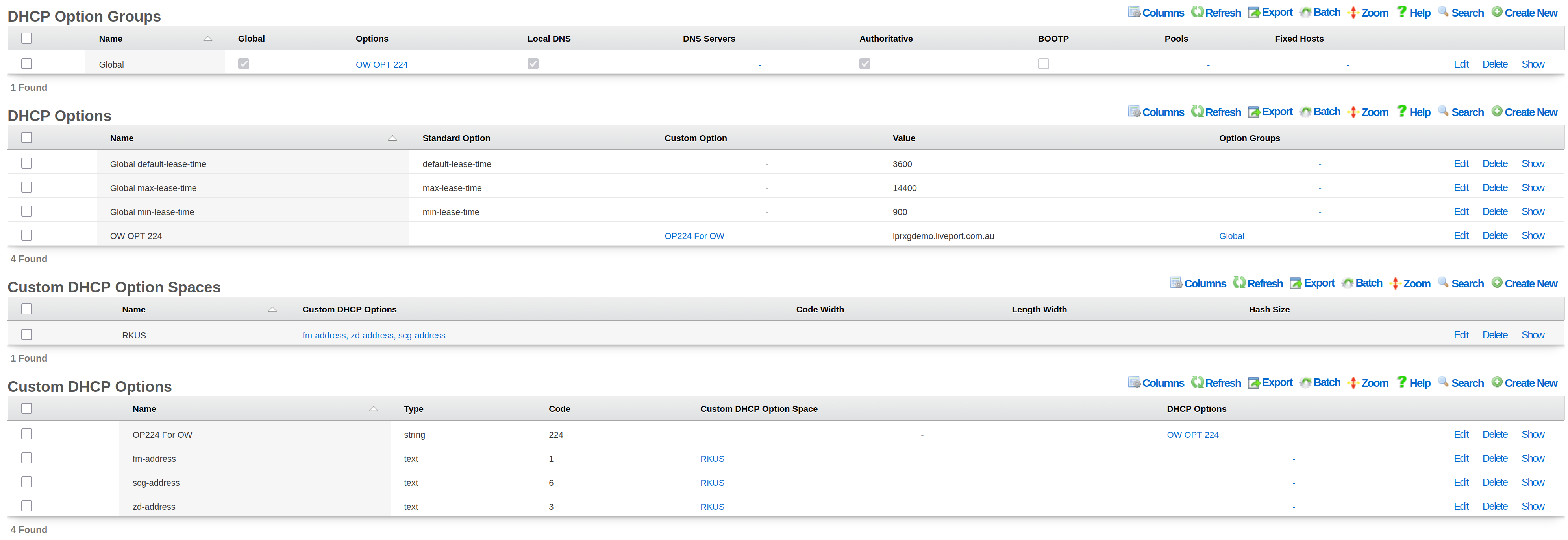
DHCP Option 224:
- Navigate to Services >> DHCP
- Confirm that a Custom DHCP Option with code 224 exists (e.g., "OP224 For OW")
- Confirm that a DHCP Option record exists (e.g., "OW OPT 224") that uses the custom option and has the rXg hostname as its value
- Verify that the DHCP Option is associated with the appropriate Option Group so that WAPs on the correct network segments receive the controller discovery address
Step 4: Verify Controller Status
- Navigate to Network >> Wireless >> WLAN Controllers
- Verify the controller shows Online status
- If offline, check the following:
- WSS Client Access Policies or WAN Targets are configured (Step 2)
- The EST Server Option is properly configured and active (Step 3)
- The rXg has a valid SSL certificate installed
- The rXg hostname is resolvable by WAPs and matches the installed SSL certificate

SDK Installation (Legacy)
Note: The SDK deployment is a legacy approach maintained for specific use cases. For new deployments, the WSS method above is recommended.
The SDK deployment uses the OpenWiFi Gateway (OWGW) running as a VM on the rXg. This approach requires virtualization support and additional system resources.
SDK Prerequisites
Hardware Requirements (minimum for < 50 WAPs): - 8 GB of memory - 8 CPU cores - 40 GB of storage - Virtualization-capable rXg hardware
Software Requirements: - An administrator account with a public SSH key defined - A physical network interface available for VM bridging
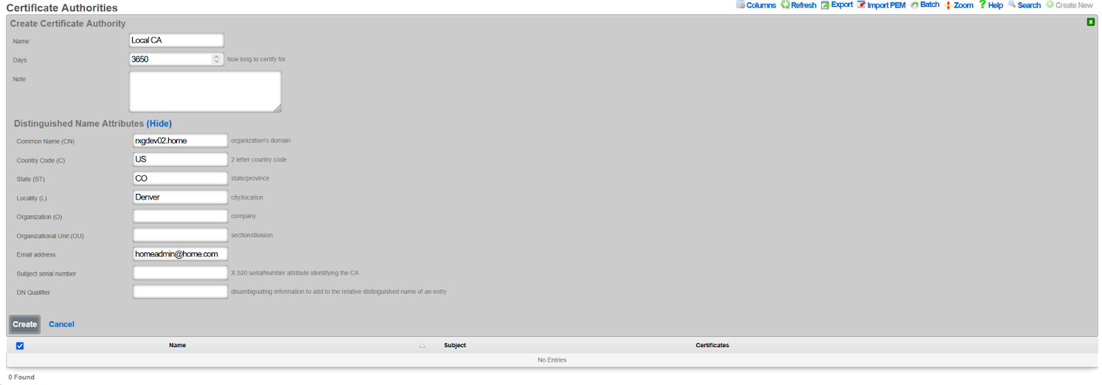
Step 1: Create a Certificate Authority
- Navigate to System >> Certificates >> Certificate Authorities
- Click Create New
- Configure the CA:
- Set lifespan to 3650 days (10 years)
- Set Common Name to match your rXg hostname
- Click Create
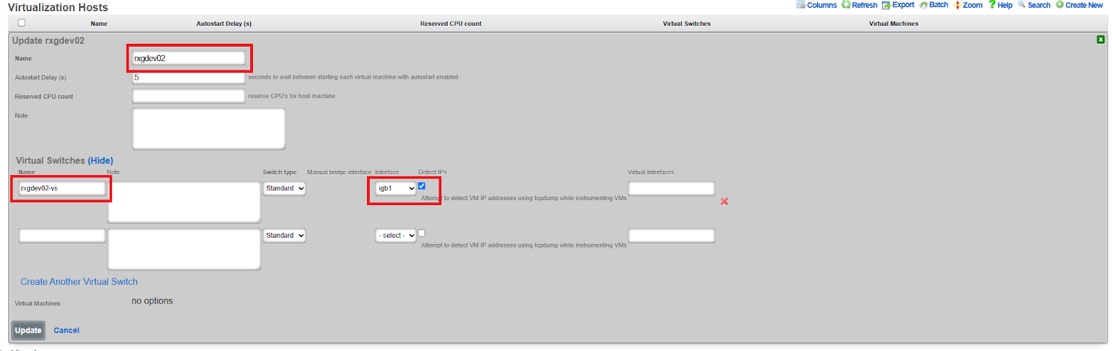
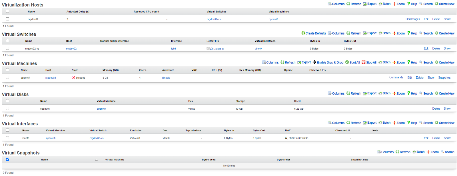
Step 2: Create a Virtualization Host
- Navigate to Services >> Virtualization >> Virtualization Hosts
- Click Create New
- Configure the virtualization host:
- Assign a physical interface (e.g.,
igb1) - Create a virtual switch name (e.g.,
rxg-openwifi-vs) - Enable Detect IPs for troubleshooting visibility
- Assign a physical interface (e.g.,
- Click Create
Step 3: Download OpenWiFi Image
- Navigate to System >> Backup >> Config Templates
- Click Show Examples
- Locate Example: 06 Download Rxg Openwifi Image Config
- Click Apply (no modifications needed)
- Monitor download progress in Services >> Virtualization >> Disk Images
- Wait for the download to complete (~2.8 GB)


Step 4: Deploy OpenWiFi Controller VM
- Navigate to System >> Backup >> Config Templates
- Locate Example: 07 Deploy Virtual Openwifi Controller
- Edit the template and modify these key variables:
<%
# Set to SDK mode
infdev_device = 'openwifi_sdk'

# VM Resources
memory_gb ||= 8
ncpu ||= 8
disk_size_gb ||= 40

# Network Configuration - match your virtual switch
mapped_switches = ["rxg-openwifi-vs"]

# IP Addressing
cidr ||= '192.168.5.5/24'
gateway ||= '192.168.5.1'
nameservers ||= '192.168.5.1'

# SSH Access - specify your SSH keypair name
ssh_keypair ||= 'My SSH Key'
ssh_user = 'openwifi-admin'
ssh_pass = 'P@ssw0rd123'
%>
- Click Apply and confirm
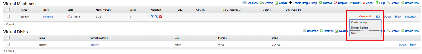
- Monitor VM creation in Services >> Virtualization >> Virtual Machines
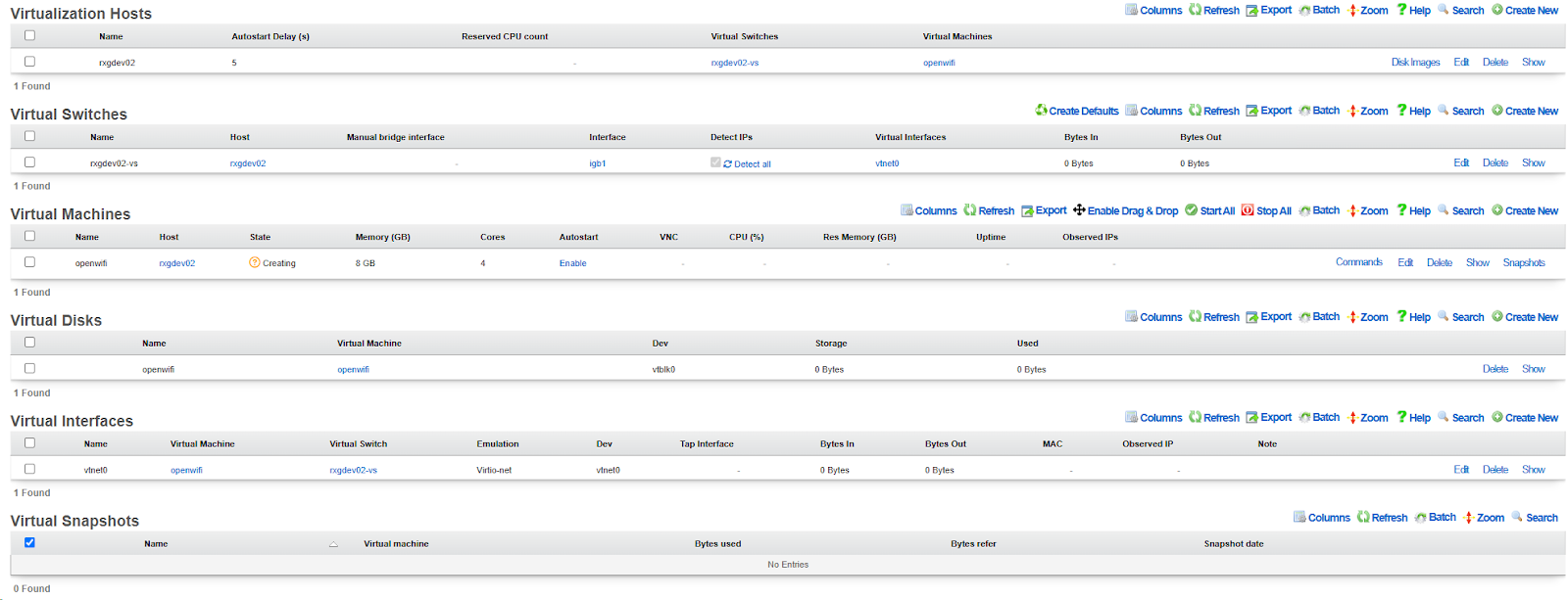
- Once created, enable Autostart for the VM
- Click Start in the Commands menu
- Allow several minutes for first boot

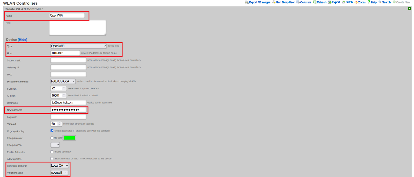
Step 5: Create WLAN Controller Integration
- Navigate to Network >> Wireless >> WLAN Controllers
- Click Create New
- Configure the controller:
- Name: Arbitrary name (e.g.,
OpenWiFi SDK) - Type: Select
OpenWiFi SDK - Host: VM IP address (e.g.,
192.168.5.5) - Password: Set a password for the API (complexity requirements apply)
- Certificate Authority: Select the CA created in Step 1
- Virtual Machine: Select the VM created in Step 4
- Enable telemetry: Check this box
- Allow updates: Check this box
- Name: Arbitrary name (e.g.,
- Click Create
The controller will initially show Offline, then transition to Online once communication with the VM is established.


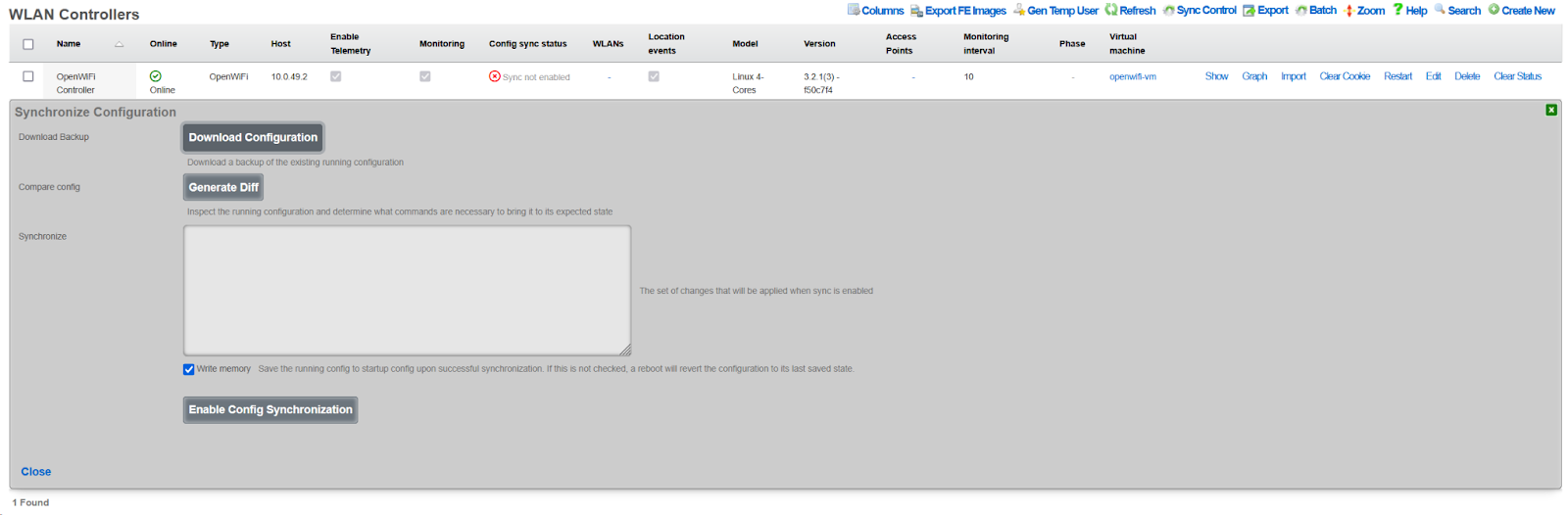
Step 6: Enable Configuration Synchronization
- Navigate to Network >> Wireless >> WLAN Controllers
- Click the Sync not enabled button (shown in red)
- Click Generate Diff
- Click Enable Config Synchronization
- Confirm manual configuration application
Configuration
After completing the WSS or SDK installation, use these steps to import WAPs and configure your wireless network.
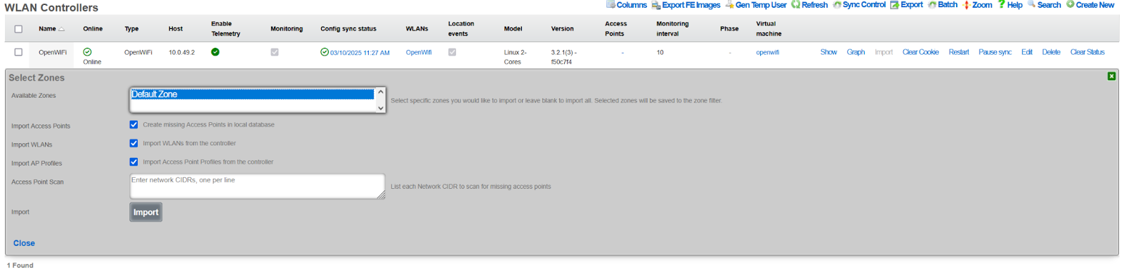
Import and Approve WAPs
- Power on the WAP in factory default state
- Ensure the WAP can acquire a DHCP address from the rXg
- Navigate to Network >> Wireless >> WLAN Controllers
- Click the Import button for the OpenWiFi controller
- Enter the WAP IP address with /32 prefix (e.g.,
10.0.47.3/32) - Click Import to begin discovery (WAP LED will blink rapidly)
- Close the dialog after import completes
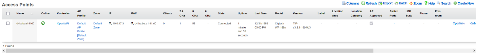
- Navigate to Network >> Wireless >> Access Points
- Click Approve on the discovered WAP
- The WAP will reboot and transition to Online status

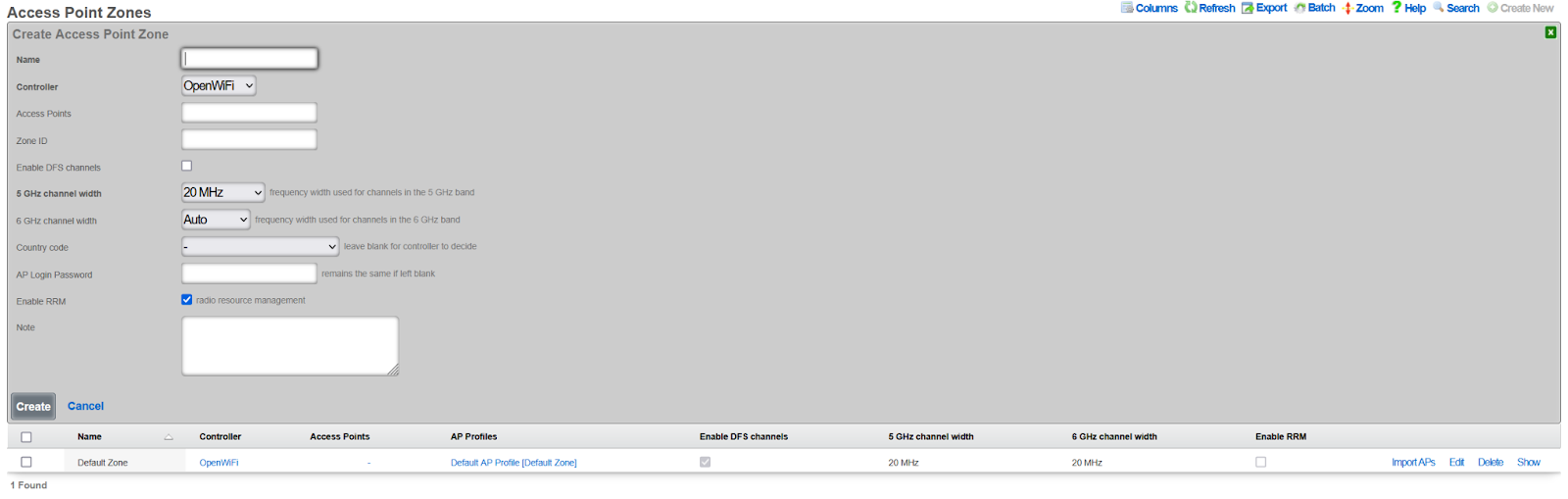
Create Access Point Zone
- Navigate to Network >> Wireless >> Access Point Zones
- Click Create New
- Configure zone settings:
- Name: Zone identifier (e.g.,
Main Building) - Controller: Select your OpenWiFi controller
- Enable DFS channels: Check if DFS channels are required
- 5 GHz channel width: 40 MHz recommended for high-density
- 6 GHz channel width: 80 MHz recommended
- Country code: Set to local country code
- Enable RRM: Leave enabled for dynamic resource management
- Name: Zone identifier (e.g.,
- Click Create
Downstream Port Configuration
OpenWiFi WSS access points with downstream (wired) Ethernet ports can be configured to provide network access to wired clients. This feature is useful for: - Guest rooms with both wireless and wired devices - Public areas with kiosks or other wired equipment - Locations where APs double as wired network extenders
Note: Downstream port configuration is only available for OpenWiFi WSS controllers. This feature is not supported in SDK mode.
Version Requirement: This feature requires OpenWiFi firmware version 4.2.0 or later. Earlier versions do not support downstream port management.
How Downstream Ports Work
The rXg WSS controller manages downstream ethernet ports through the rg_wss_client Python application running on each access point. The system automatically detects available LAN ports from the AP's hardware capabilities and configures them based on the selected VLAN mode.
Technical Implementation:
- Port Detection: LAN ports are automatically discovered from
/etc/ucentral/capabilities.jsonon the AP - Bridge Integration: In static VLAN mode, downstream ports are added to the upstream bridge alongside wireless clients
- VLAN Tagging: Bridge VLAN filtering (802.1Q) tags untagged ingress packets from wired clients
- Port Cycling: After configuration, ports are cycled (brought down, then up) to force clients to reconnect with correct VLAN settings
- State Management: Downstream port configuration is pushed to APs via the WebSocket state message
Supported Scenarios:
| Scenario | Wireless | Wired | Tunnel | Use Case |
|---|---|---|---|---|
| RADIUS + Tunnel | RADIUS dynamic VLAN | 802.1X MAC auth | Yes | Enterprise with both wireless and wired authentication |
| Static + Tunnel | Static VLAN (from SSID) | Static VLAN (from room) | Yes | Hotel rooms with tunneling |
| Static + No Tunnel | Static VLAN (from SSID) | Static VLAN (from room) | No | Local bridging without tunneling |
| RADIUS + No Tunnel | RADIUS dynamic VLAN | 802.1X MAC auth | No | Local enterprise network |
Downstream Port VLAN Modes
Three modes are available for downstream port configuration:
Disabled (default) - Downstream ports are not configured - No wired client access is provided - This is the default setting for new zones
RADIUS MAC Authentication - Uses IEEE 802.1X MAC-based authentication - APs act as authenticators, forwarding MAC addresses to the RADIUS server - VLAN assignment is determined dynamically by RADIUS server responses - Requires: - RADIUS server configured in RGConsole - RADIUS policies that assign VLANs based on MAC address - Use case: Dynamic VLAN assignment based on device identity
Static VLAN from Room - Assigns wired clients to the same VLAN as the associated PMS room - Wired clients send untagged traffic; the AP applies VLAN tagging via bridge filtering - Requires: - AP associated with a PMS room - Room configured with VLAN tag assignment - Optional tunnel configuration for traffic encapsulation - Use case: Guest room wired devices on same network as wireless devices
Technical Details - Static VLAN Mode:
In static VLAN mode, the system uses Linux bridge VLAN filtering to tag untagged traffic from wired clients:
Port Configuration:
- Downstream port (e.g.,
eth1) is added to the upstream bridgeup - Bridge VLAN configuration applies PVID (Port VLAN ID) with "untagged" flag
- Example:
bridge vlan add vid 303 dev eth1 pvid untagged
- Downstream port (e.g.,
Traffic Flow:
- Ingress (wired AP): Untagged packets from wired clients are tagged with the configured VLAN ID
- Egress (AP wired): VLAN tags are stripped before forwarding to wired clients
- Wireless clients: Continue to use dynamic VLAN assignment via RADIUS (if configured)
Tunnel Compatibility:
- When tunneling is enabled, the system avoids creating a downstream bridge in uCentral config
- This prevents
gre4t-gre.{vlan}interfaces from intercepting VLAN-tagged traffic - Instead,
rg_wss_clientmanages the downstream port directly using bridge VLAN filtering - Both wireless RADIUS clients and wired static VLAN clients can coexist on the same VLAN
Automatic Reconnection:
- After applying bridge VLAN configuration, the system cycles the downstream port (down/up)
- This forces connected clients to acquire fresh DHCP leases with correct VLAN configuration
- Eliminates the need for manual client reconnection after AP configuration changes
Example Configuration Flow:
1. AP assigned to PMS Room 101
2. Room 101 has Account with VLAN 303 assignment
3. Downstream port has SwitchPortProfile with:
   - radius_authentication='none'
   - native_vlan=303
4. rXg generates state with: downstream_port_config={'LAN': {'mode': 'static', 'vlan': 303}}
5. rg_wss_client on AP:
   - Detects eth1 from capabilities.json
   - Adds eth1 to bridge 'up'
   - Configures: bridge vlan add vid 303 dev eth1 pvid untagged
   - Cycles eth1 down/up (only on first configuration)
6. Wired PC connects and gets DHCP lease on VLAN 303
7. Wireless phone connects via RADIUS and gets dynamic VLAN (can be same or different)
Per-Port Configuration via SwitchPortProfile
Downstream ports are configured individually using SwitchPortProfile:
Creating a Profile for RADIUS Mode:
- Navigate to Network >> Switching >> Switch Port Profiles
- Create a new profile or edit existing one
- Set RADIUS Authentication to MAC Authentication Bypass
- Leave Native VLAN empty
- Click Create or Update
Creating a Profile for Static VLAN Mode:
- Navigate to Network >> Switching >> Switch Port Profiles
- Create a new profile or edit existing one
- Set RADIUS Authentication to none
- Set Native VLAN to desired VLAN ID (e.g., 303)
- Click Create or Update
Assigning Profile to Downstream Port:
- Navigate to Network >> Switching >> Switch Ports
- Find the AP's downstream port (port_type: ap_downstream)
- Edit the port
- Select the desired Switch Port Profile
- Click Update
The configuration automatically pushes to the AP when the profile is saved.
Configuration Notes
- Downstream port configuration requires compatible AP hardware with downstream ethernet ports
- Each downstream port can have its own independent configuration via different profiles
- Multiple ports can share the same profile for consistent configuration
- Automatic Port Detection: LAN ports are detected from AP hardware capabilities; no manual port specification needed
- Mixed Deployments: Per-AP overrides allow different modes in different areas (e.g., RADIUS in offices, Static in guest rooms)
- Automatic Reconfiguration: Changes to downstream port mode trigger immediate AP reconfiguration via WebSocket
- RADIUS Requirements: Authentication server must be reachable from AP management network
- Static Mode Requirements: Requires AP assigned to PMS room with VLAN tag assignment; silently disabled otherwise
- Port Cycling: After configuration, ports are automatically cycled to force client DHCP renewal
- Tunnel Compatibility: Static VLAN mode works with or without tunneling
AP Login Password (OpenWiFi WSS)
The AP Login Password field allows you to configure SSH root access passwords for access points at three levels of specificity: per-AP, zone-level, and device-level. The system uses a hierarchy from most specific to least specific.
Password Hierarchy (Most Specific Least Specific):
- Per-AP Password: Individual access point override (highest priority)
- Zone Password: All access points in a specific zone
- Infrastructure Device Password: All access points on the wireless controller
- Default Password:
openwifi(when no password is configured at any level)
Configuration Locations:
Per-AP Password (Individual Access Point): 1. Navigate to Network >> Wireless >> Access Points 2. Edit a specific OpenWiFi WSS access point 3. Enter a password in the AP Login Password field 4. This password takes precedence over zone and device-level passwords
Zone Password (All APs in Zone): 1. Navigate to Network >> Wireless >> Access Point Zones 2. Edit an existing OpenWiFi WSS zone or create a new one 3. Enter a password in the AP Login Password field 4. This password applies to all APs in the zone (unless overridden at AP level)
Infrastructure Device Password (All APs on Controller): 1. Navigate to Network >> Wireless >> Wireless Devices 2. Edit the OpenWiFi WSS wireless device 3. Enter a password in the AP Login Password field 4. This password applies to all APs on this controller (unless overridden at zone or AP level)
General Notes:
- This feature is available for: OpenWiFi WSS, OpenWiFi SDK, Ruckus, and Omada wireless devices
- Password changes trigger a configuration sync to affected WAPs
- Minimum password length: 8 characters
- Empty strings are ignored (treated as if no password is set)
OpenWiFi-specific behavior:
- The username is always
root- only the password is configurable - Leave the field blank to use default credentials (
openwifi) - SSH access example:
bash
ssh root@<wap-ip-address>
# Enter the configured password (per-AP, zone, or device-level)
Ruckus/Omada behavior:
- Both username and password are configurable (use the AP Login Name field for username)
- Credentials are required - there is no default fallback
SSID Quality Thresholds
OpenWiFi zones support SSID quality thresholds that allow operators to control client connectivity based on signal strength. These settings help maintain network quality by preventing weak clients from degrading overall performance.
Available Thresholds:
Probe Request RSSI: Minimum RSSI (dBm) for probe requests to be accepted. Probe requests below this threshold will be ignored by the WAP. Leave blank to accept all probe requests.
Association Request RSSI: Minimum RSSI (dBm) for association requests to be accepted. Clients with signal strength below this threshold will be denied association. Leave blank to accept all associations.
Client Kick RSSI: Minimum RSSI (dBm) threshold for connected clients. Clients whose signal drops below this value will be disconnected from the WAP. Leave blank to disable client kicking.
Client Kick Ban Time: Duration in seconds that a kicked client is banned from re-joining the same SSID. Set to 0 or leave blank for no ban (client can immediately attempt to reconnect). This field is only visible when Client Kick RSSI is configured.
Configuration:
Quality thresholds are configured at the Access Point Zone level and apply to all WLANs and WAPs in that zone. Navigate to Wireless Access Point Zones, edit an OpenWiFi zone, and configure the threshold values.
Example Values:
Probe Request RSSI: -75
Association Request RSSI: -70
Client Kick RSSI: -80
Client Kick Ban Time: 60
In this configuration: - Probe requests weaker than -75 dBm are ignored - Associations weaker than -70 dBm are denied - Connected clients dropping below -80 dBm are kicked - Kicked clients are banned for 60 seconds before they can reconnect
Use Cases:
Dense Deployments: In high-density environments with many overlapping APs, use quality thresholds to encourage clients to roam to closer APs rather than staying connected to distant ones.
Capacity Management: Prevent weak clients from consuming excessive airtime by setting association and kick thresholds.
Band Steering: Use different thresholds on 2.4 GHz vs 5 GHz to encourage dual-band clients to prefer 5 GHz.
Validation Rules:
- RSSI values must be negative integers (e.g., -70, -75, -80). Positive or zero values are rejected.
- Ban time must be a non-negative integer (0 or greater). A value of 0 means no ban.
- All fields are optional leave blank to disable that threshold.
Important Notes:
- These thresholds are based on the OpenWiFi uCentral
interface.ssid.quality-thresholdsschema - Threshold values are in dBm (negative numbers, e.g., -70, -75, -80)
- More negative values represent weaker signals (e.g., -80 is weaker than -70)
- Aggressive thresholds can cause connectivity issues - start with conservative values and adjust based on monitoring
- Quality thresholds apply per-SSID and are evaluated independently for each radio band
Per-Radio Client Limits
Access Point Zones support per-radio maximum client limits for load balancing. These limits control how many wireless clients can associate with each radio band across all WAPs in the zone.
Configuration Fields:
| Field | Description |
|---|---|
| Maximum Clients 2.4 GHz | Maximum clients per 2.4 GHz radio, accumulative across all SSIDs on that radio |
| Maximum Clients 5 GHz | Maximum clients per 5 GHz radio, accumulative across all SSIDs on that radio |
| Maximum Clients 6 GHz | Maximum clients per 6 GHz radio, accumulative across all SSIDs on that radio (only shown if controller supports 6 GHz) |
| Ignore Probe Requests | When enabled, the radio will not respond to probe requests from new clients once the limit is reached |
Behavior:
- When a radio reaches its maximum client limit, new association requests are rejected
- When Ignore Probe Requests is enabled, the radio stops responding to probe requests, causing clients to not see the network and naturally steer to other WAPs or radios
- Setting a field to blank (null) means no limit is enforced for that band
- These limits are accumulative across all SSIDs (VAPs) attached to the radio e.g., a limit of 64 means 64 total clients across all SSIDs on that radio, not 64 per SSID
Defaults and Recommendations:
When no limit is configured (field left blank), the radio accepts clients up to hardware/firmware capacity (typically 127-128 per radio). This is suitable for most deployments.
| Deployment Type | Recommended Limit | Notes |
|---|---|---|
| High-density (stadiums, conference halls) | 30-50 per radio | Ensures acceptable per-client throughput |
| Medium-density (hotels, offices) | 50-60 per radio | Balances capacity with airtime fairness |
| Low-density (small offices, retail) | Leave blank | Hardware limits are sufficient |
Use Cases:
- High-density venues: Prevent any single radio from becoming overloaded
- Load distribution: Encourage clients to distribute across multiple WAPs
- Quality of service: Maintain acceptable per-client throughput by limiting radio congestion
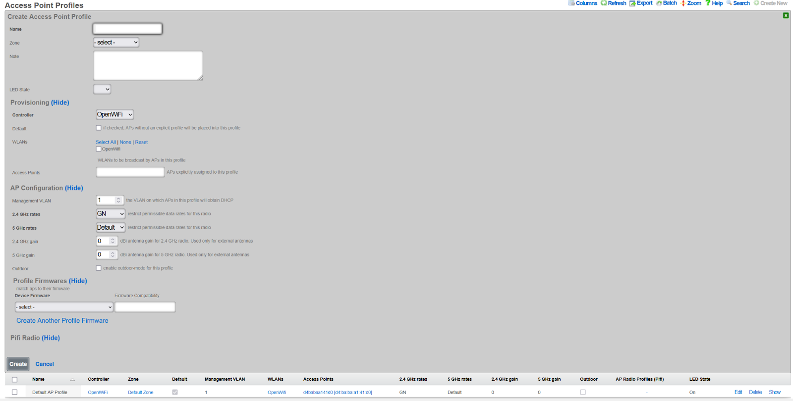
Create Access Point Profile
- Navigate to Network >> Wireless >> Access Point Profiles
- Click Create New
- Configure profile settings:
- Name: Profile identifier (e.g.,
Standard Profile) - Zone: Select the zone created above
- Controller: Select your OpenWiFi controller
- Default: Check to make this the default profile
- LED State: On or Off per preference
- Name: Profile identifier (e.g.,
- Click Create
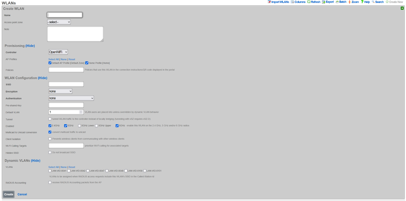
Create WLAN
- Navigate to Network >> Wireless >> WLANs
- Click Create New
- Configure WLAN settings:
- Name: WLAN identifier (not the SSID)
- SSID: The broadcast network name
- Controller: Select your OpenWiFi controller
- Zone: Select your zone
- AP Profiles: Select profiles to include this WLAN
- Encryption: WPA3 recommended. Note: WPA2/3 mixed is not supported for OpenWiFi.
- Authentication: Select appropriate method
- PSK: Enter pre-shared key if applicable
- Enabled bands: Select 2.4 GHz, 5 GHz, and/or 6 GHz
- Max Client Limit: Optional limit on clients that may connect to this specific SSID/VAP (OpenWiFi only)
- Click Create
Per-SSID Client Limit
OpenWiFi WLANs support a per-SSID maximum client limit. This limit controls how many wireless clients can associate with this specific SSID across all radios on a WAP.
Configuration:
- Maximum Clients: Set the maximum number of clients allowed on this SSID per WAP. Leave blank for no limit.
Behavior:
- When the limit is reached, new association requests for this SSID are rejected
- The limit applies per-WAP, not globally across all WAPs
- This limit is independent of per-radio limits configured at the zone level
- Both limits can be used together for fine-grained control
- When left blank, no limit is enforced and clients can connect up to hardware capacity
Interaction with Per-Radio Limits:
When both per-SSID and per-radio limits are configured, the lower limit takes effect first. For example, if a radio limit is set to 50 and the SSID limit is set to 30, the SSID will reject clients at 30 even though the radio could still accept more on a different SSID.
Use Cases:
- Service tiers: Limit a guest SSID to fewer clients than a premium SSID
- Capacity planning: Ensure no single SSID dominates WAP resources
- Fair access: Distribute clients across multiple SSIDs
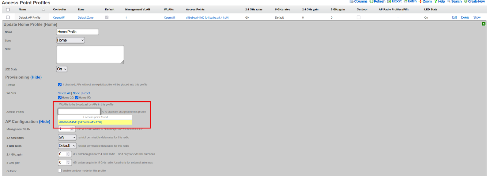
Assign WAPs to Profile
- Navigate to Network >> Wireless >> Access Point Profiles
- Edit the target profile
- Select WAPs in the Access Points field
- Click Update
- WAPs will reboot and begin broadcasting the configured SSIDs
Operations
This section covers the day-to-day operational aspects of managing OpenWiFi WAPs.
Discovery and Adoption
The rXg can discover OpenWiFi WAPs using one of three methods: Direct IP Scanning, MAC prefix matching, or via the App. Once a WAP is discovered, the rXg initiates an automated import process that upgrades the device's firmware and provisions it with an rXg-signed certificate. No further operator intervention is needed to bring the device online.
Default Radio Status
The OpenWiFi WSS controller provides a "Default Radio Status" setting for each radio band (2.4 GHz, 5 GHz, and 6 GHz) to control the initial state of radios on newly adopted WAPs. This feature is especially useful in production environments with large numbers of WAPs.
Available Options:
- Disabled (default): New WAPs will have their radios disabled and must be manually enabled by the operator.
- Auto: New WAPs will have their radios automatically enabled upon adoption.
Configuration:
The default radio status can be configured per band in the WLAN Controller settings under the "Wireless" section.
Behavior:
- When set to "Disabled" (or left unset), newly adopted WAPs will require manual intervention to enable radios.
- When set to "Auto", newly adopted WAPs will have radios enabled automatically, allowing them to begin serving clients immediately after adoption.
- This setting only applies to new WAPs at the time of adoption. Existing WAPs are not affected by changes to this setting.
- Radio status can always be overridden on a per-WAP basis after adoption using the WAP's channel override settings.
Configuration Synchronization
After adoption, the WAP can be configured through the rXg's vendor-neutral interface. When an administrator makes a change on the rXg, the rXg immediately pushes the latest configuration state down to the WAP via the WSS connection. The WAP is then responsible for applying this new state.
Per-WAP GRE Endpoint Override
OpenWiFi WSS WAPs support per-WAP tunnel endpoint overrides, allowing individual WAPs to tunnel traffic to different tunnel endpoints while sharing the same WLAN configurations.
How It Works:
- WLANs define a default tunnel endpoint (
gre_tunnel_gateway_ip) that applies to all WAPs broadcasting that WLAN - Individual WAPs can override this setting with their own
gre_endpointvalue - When a WAP has a
gre_endpointconfigured, it takes precedence over the WLAN's default tunnel endpoint for all tunneled WLANs on that WAP - If the WAP's
gre_endpointis not set, the WLAN'sgre_tunnel_gateway_ipis used (standard behavior)
Use Cases:
- Routing traffic from specific WAPs to regional aggregation points
- Testing new tunnel endpoints on a subset of WAPs before widespread deployment
- Implementing site-specific or building-specific traffic routing policies
- Multi-tenant scenarios where different WAPs need to tunnel to different controllers
Configuration:
The GRE Endpoint field is available in the Access Points scaffold (Wireless -> Access Points) and is only editable for OpenWiFi WSS access points. The field accepts an IPv4 or IPv6 address and will override the WLAN's tunnel endpoint for all tunneled traffic from that WAP.
This feature follows the same override pattern as TX power settings: zone-level defaults can be overridden at the profile level, which can then be overridden at the individual WAP level.
Monitoring and Telemetry
The rXg uses the persistent WSS connection to monitor the WAP's health. - If a WAP becomes unsubscribed, the rXg marks it as offline and creates a health notice which it will send out to network operators. - The WAP client periodically sends telemetry data--such as Wi-Fi scans, current configuration, and firmware version--back to the rXg.
LED Status Indicators
OpenWiFi WAPs use LED patterns to indicate system status and connectivity issues. The LED system follows a priority hierarchy where higher-priority issues override lower-priority indicators.
Hardware Limitations:
Note: Some WAP models have hardware limitations that affect LED status indication:
Single-color LED models (e.g., CIG 188N): These devices have only a single-color LED and cannot display the color-coded status patterns described below. On these models, LED status indication is not available.
Non-ideal color reproduction (e.g., EdgeCore EAP111): Some models have LEDs with poor color accuracy, making it difficult to distinguish between certain colors (e.g., cyan vs. blue, or yellow vs. green). When troubleshooting these devices, consider using other diagnostic methods such as the rXg interface or SSH access rather than relying solely on LED colors.
LED Priority Hierarchy:
| Priority | LED Pattern | Meaning | Notes |
|---|---|---|---|
| 0 | White blink (1x/sec) | rxg_sdan dataplane unavailable | Highest priority. The kernel-module dataplane (rxg_sdan) failed to initialize, so the WAP passes no client traffic; the WSS control plane stays connected so the WAP remains manageable from the rXg. A CRITICAL message is also sent to syslog. Distinct from the temporary white rapid "locate" blink (see Manual LED Blink below). |
| 1 | Red blink (2x/sec) | Gateway unreachable | Data plane failure |
| 2a | Blue blink (1x/sec) | WebSocket disconnected | Management plane failure |
| 2b | Slow blue blink (every 2s) | Subscribed, awaiting initial configuration from rXg | Channel is up but the rXg has not pushed the AP's state yet; the AP re-requests it every 60s. Distinct from the faster 2a blink. |
| 2c | Yellow blink (1x/sec) | RADIUS unreachable | Control plane failure |
| 2d | Cyan blink (1x/sec) | EST server unreachable | Certificate management failure (when enabled) |
| 3 | Tunnel-Specific States (when a tunnel is configured): | ||
| Solid blue | Clients connected + traffic flowing | Active tunnel traffic | |
| Solid magenta | Clients connected + no traffic | Idle tunnel clients | |
| Solid green | No clients connected | tunnel ready | |
| 3 | Standard States (when no tunnel is configured): | ||
| Solid blue | Stations connected | Active service | |
| Solid green | Ready, no stations | Idle state | |
| 4 | LED off | LEDs disabled |
Special States:
- All Colors Alternating "Disco Blink": Working on downloading
rg_wss_clientmanagement software from rXg. - Error states always display: Blinking patterns (white/red/blue/yellow/cyan) show regardless of LED configuration for troubleshooting
Key Behaviors:
- Higher priority issues always override lower priority indicators
- Tunnel configurations use special LED states to indicate tunnel health and client activity
- Solid LEDs respect the
unit.leds-activeconfiguration setting - Error indicators (blinking patterns) always display for visibility
- EST server monitoring only activates during certificate management operations
Manual LED Blink
OpenWiFi WAPs support a manual blink feature that helps operators physically identify specific WAPs in large deployments. When triggered from the rXg, the WAP will blink its LED rapidly in white for 5 minutes, overriding all normal LED monitoring behavior.
LED Configuration:
- On: LED system fully active (error states + solid OK states)
- Off: LED system shows only error states (white/red/blue/yellow/cyan blinks), suppresses solid OK states
Note: "Blink" is not available as a persistent LED configuration optionit is a temporary manual action only.
Manual Blink Behavior:
- Triggers rapid white LED blink for 5 minutes
- Overrides all normal LED monitoring during this period
- Automatically expires after 5 minutes and returns to normal monitoring
- Can be immediately cancelled by clicking "LED On" or "LED Off" buttons
- Status is shown in the rXg interface with a live countdown timer
Use Case: When managing multiple WAPs in a venue, operators can use the manual blink feature to quickly locate a specific WAP by triggering the distinctive white rapid blink pattern from the rXg interface.
Client Experience Ping Monitoring
OpenWiFi WSS WAPs can perform connectivity monitoring from the client's perspective by simulating real client traffic through the tunnel. This feature helps operators verify that clients would experience proper network connectivity.
How It Works:
The client experience monitoring system performs periodic ping tests that simulate actual client traffic:
- Tunnel-encapsulated Pings: Pings are sent as Tunnel-encapsulated packets through the same tunnel that client traffic uses
- DHCP Acquisition: The WAP acquires a DHCP lease on the test VLAN to obtain a valid client IP address
- DNS Resolution: Target hostnames are resolved to IP addresses with DNS caching (5-minute TTL) to reduce resolver load
- Custom Targets: Operators configure which domains or IP addresses to test (comma-separated list)
- MAC-Based Timing: Pings are staggered across the WAP fleet using MAC-based timing offsets (0-59 seconds) to prevent network spikes
- Telemetry Reporting: Results are reported back to the rXg via the telemetry system with packet loss, latency, and jitter metrics
Configuration:
Client experience ping monitoring is configured at the Access Point Zone level and applies to all WAPs in that zone. The configuration is only available for OpenWiFi WSS zones.
Navigate to Wireless Access Point Zones, edit an OpenWiFi WSS zone, and configure:
- Enable Client Experience Pings: Checkbox to enable/disable the client experience ping monitoring
- Enable Underlay Gateway Pings: Checkbox to enable/disable pings to the underlay gateway (the physical network gateway)
- Client Experience Ping Targets: Comma-separated list of domains or IP addresses to ping (e.g.,
google.com, 8.8.8.8, cloudflare.com)
Important Notes:
- Targets must be explicitly configured - there are no default ping targets
- Client experience pings will only run when enabled and targets are configured
- The WAP must have a test VLAN ID configured (from an account associated with the WAP's PMS room)
- Pings require tunnel configuration to be present on the WAP
- Invalid targets (malformed domains/IPs) are rejected by validation
Room Size Limit:
To prevent DHCP pool exhaustion on test VLANs, client experience monitoring is automatically disabled for rooms containing 25 or more WAPs. This limit protects deployments with many "common area" WAPs (lobbies, conference centers, ballrooms) that share a single test VLAN.
When a room reaches this threshold:
- All WAPs in that room will have test_vlan_id: nil in their state
- Client experience pings will not run on any WAP in that room
- Underlay gateway pings will continue to function normally
- The WAP will log: "No test VLAN ID configured in AP state"
This limit is defined by the constant MAX_APS_PER_ROOM_FOR_MONITORING = 25 in console/app/models/concerns/openwifi/configuration_management.rb.
Why This Limit Exists:
Each WAP performing client experience monitoring acquires a DHCP lease on the test VLAN. In typical hotel deployments, guest rooms have 1-2 WAPs and share a VLAN through their account assignment. However, large common areas (conference centers, ballrooms, lobbies) may have dozens of WAPs assigned to a single non-resident "house" account.
Without this limit, 50+ WAPs in a ballroom could exhaust a /24 test VLAN's DHCP pool, preventing legitimate client traffic or causing monitoring failures. The 25 AP threshold provides sufficient protection while allowing monitoring in most scenarios.
Prerequisites for Monitoring:
Client experience monitoring will only run when ALL of the following conditions are met:
Zone Configuration:
- "Enable Client Experience Pings" is checked in the Access Point Zone
- "Client Experience Ping Targets" field contains valid targets
WAP Assignment:
- WAP is assigned to a PMS Room (Wireless >> Access Points >> edit >> PMS Room field)
Account Association:
- The PMS Room has at least one associated Account
VLAN Configuration:
- The Account has a VLAN Tag Assignment
- The VLAN must belong to a tunnel pseudo interface (client experience pings require tunnel encapsulation)
Room Size:
- The PMS Room contains fewer than 25 WAPs
- If the room has 25+ WAPs, monitoring is automatically disabled to prevent DHCP pool exhaustion
Tunnel:
- At least one WLAN on the WAP must have tunneling configured
- The test VLAN uses tunnel encapsulation to reach the rXg
To verify these prerequisites, check the AP state message for test_vlan_id. If nil, one or more prerequisites are not met.
Example Configuration:
Enable Client Experience Pings:  (checked)
Enable Underlay Gateway Pings:  (checked)
Client Experience Ping Targets: google.com, youtube.com, 1.1.1.1
Monitoring Results:
Ping results are available in the telemetry system and include: - Success/failure status - Packet loss percentage - Average, minimum, and maximum round-trip time (RTT) - Jitter measurements - Target domain/IP being tested - DHCP-acquired client IP and gateway information
LED Feedback:
When all client experience ping tests fail, the WAP will show a magenta blinking LED pattern to indicate the connectivity issue. This provides immediate visual feedback to operators about client experience problems.
Key Performance Indicators (KPIs)
The rXg collects and stores detailed performance metrics from OpenWiFi WAPs. These Key Performance Indicators (KPIs) provide visibility into wireless network health, client experience, and radio performance. KPIs are collected at two levels: per-client metrics and per-radio aggregated metrics.
Data Collection
KPIs are extracted from state messages sent by WAPs via the persistent WSS connection. The rXg processes these messages in real-time, storing metrics in TimescaleDB for efficient time-series analysis.
Collection Frequency: State messages are sent periodically by WAPs (typically every 60 seconds).
Data Retention:
| Resolution | Retention Period |
|---|---|
| Full resolution | 3 days |
| 15-minute averages | 1 week |
| 30-minute averages | 2 weeks |
| 1-hour averages | 30 days |
| 2-hour averages | 1 year |
| 1-day averages | 10 years |
Client KPIs
Client KPIs are collected for each individual wireless client connected to a WAP. These metrics help diagnose individual device connectivity issues and track client experience.
| Metric | Unit | Description |
|---|---|---|
| SNR | dB | Signal-to-Noise Ratio. Measures the quality of the wireless signal relative to background noise. Higher values indicate better signal quality. |
| RSSI | dBm | Received Signal Strength Indicator. The absolute signal power received by the WAP from the client. Values closer to 0 are stronger. |
| Bytes To Client | bytes | Payload bytes transmitted from the WAP to the client in the sampling interval. |
| Bytes From Client | bytes | Payload bytes received by the WAP from the client in the sampling interval. |
| Cumulative Bytes To Client | bytes | Total payload bytes transmitted to the client since association. |
| Cumulative Bytes From Client | bytes | Total payload bytes received from the client since association. |
| Throughput Rate To Client | bps | Current data rate from WAP to client (download). |
| Throughput Rate From Client | bps | Current data rate from client to WAP (upload). |
| TX Link Speed | Mb/s | Negotiated transmit link speed from WAP to client. |
| RX Link Speed | Mb/s | Negotiated receive link speed from client to WAP. |
| TX MCS | index | Transmit Modulation and Coding Scheme index. Higher values indicate faster potential speeds. |
| RX MCS | index | Receive Modulation and Coding Scheme index. |
| Channel | number | The channel on which the client is connected. |
| NSS | count | Number of Spatial Streams in use. More streams enable higher throughput. |
| PHY | string | Physical layer standard (e.g., "802.11ax", "802.11ac"). Indicates the Wi-Fi generation. |
| TX PER | % | Transmit Packet Error Rate. Percentage of transmitted packets that failed. |
| Cumulative TX Packets | count | Total packets transmitted to the client since association. |
| Cumulative TX Failed | count | Total failed packet transmissions since association. Used for packet loss calculation. |
Signal Quality Reference:
| SNR Value | Quality Assessment |
|---|---|
| 40 dB | Excellent |
| 30 dB | Very Good |
| 20 dB | Good (adequate for connection) |
| < 20 dB | Poor (inadequate for reliable WiFi) |
| RSSI Value | Quality Assessment |
|---|---|
| -70 dBm | Good (reliable WiFi) |
| -70 to -80 dBm | Fair (intermittent issues possible) |
| -90 dBm | Poor (inadequate for WiFi) |
Radio KPIs
Radio KPIs are aggregated metrics calculated across all clients connected to a specific radio. These metrics provide a high-level view of radio performance and capacity utilization.
Client and Capacity Metrics
| Metric | Unit | Description |
|---|---|---|
| Client Count | clients | Number of clients currently connected to the radio. |
| Channel Utilization | % | Percentage of airtime being used on the channel. High values indicate congestion. |
| TX Channel Utilization | % | Percentage of airtime used for transmitting. |
| RX Channel Utilization | % | Percentage of airtime used for receiving. |
Capacity Reference:
| Client Count | Assessment |
|---|---|
| < 50 | Normal |
| 50-60 | Warning (approaching capacity) |
| > 60 | Critical (overloaded) |
| Channel Utilization | Assessment |
|---|---|
| < 85% | Normal |
| 85-90% | Warning |
| > 90% | Critical (congested) |
Signal Quality Aggregates
For each signal quality metric, the rXg calculates statistical aggregates across all connected clients:
| Metric | Unit | Description |
|---|---|---|
| RSSI Min/Max/Avg/Stddev | dBm | Statistical distribution of RSSI values across all clients. |
| SNR Min/Max/Avg/Stddev | dB | Statistical distribution of SNR values across all clients. |
| Noise Floor | dBm | Environmental RF noise level detected by the radio. Lower (more negative) values indicate a cleaner RF environment. |
Link Speed and MCS Aggregates
| Metric | Unit | Description |
|---|---|---|
| Speed Min/Max/Avg/Stddev | Mb/s | Statistical distribution of negotiated link speeds across all clients. |
| MCS Negotiated Min/Max/Avg/Stddev | index | Statistical distribution of MCS indices across all clients. |
MCS Reference:
| Average MCS | Assessment |
|---|---|
| > 5 | Normal |
| 2-5 | Warning |
| 1 | Critical (severe performance issues) |
Throughput Aggregates
| Metric | Unit | Description |
|---|---|---|
| TP Min/Max/Avg/Stddev | Mb/s | Throughput from WAP to clients (TX only). Statistical distribution across all clients. |
| Agg TP Min/Max/Avg/Stddev | Mb/s | Aggregate throughput (TX + RX combined). Statistical distribution across all clients. |
Throughput Reference (per radio):
| Aggregate Throughput | Assessment |
|---|---|
| < 1 Gb/s | Normal |
| 1-1.5 Gb/s | Warning |
| > 1.5 Gb/s | Critical (approaching radio limits) |
Packet Loss Aggregates
| Metric | Unit | Description |
|---|---|---|
| PL Min/Max/Avg/Stddev | % | Packet loss percentage. Statistical distribution across all clients. |
Channel and Radio Configuration
| Metric | Unit | Description |
|---|---|---|
| Channel 2.4 | number | Current 2.4 GHz channel. |
| Channel 5 | number | Current 5 GHz channel. |
| Channel 6 | number | Current 6 GHz channel. |
| Channel Str | string | Channel representation for bonded frequencies (e.g., "116, 120"). |
| Frequency Str | string | Operating frequencies in MHz (e.g., "5580, 5600"). |
| Channel Width | MHz | Current channel width (20, 40, 80, 160 MHz). |
| TX Power | dBm | Transmit power level before antenna gain. |
| Gain | dB | Antenna gain applied to the signal. |
Data Volume Metrics
| Metric | Unit | Description |
|---|---|---|
| TX Bytes | bytes | Total bytes transmitted by the radio to clients. |
| RX Bytes | bytes | Total bytes received by the radio from clients. |
| TX Packets | count | Total packets transmitted by the radio. |
| RX Packets | count | Total packets received by the radio. |
Viewing KPIs
KPIs can be viewed in several locations within the rXg interface:
Access Points Dashboard: Navigate to Network >> Wireless >> Access Points to see real-time KPI summaries for each WAP.
Radio Metric Graphs: Click on an individual WAP to view time-series graphs of radio KPIs.
KPI Dialogs: Real-time dashboard widgets displaying current KPI values.
Heatmaps: Visual representation of KPIs across floor plans. Available metrics for heatmaps include:
- Client Count
- Average SNR
- Average RSSI
- Noise Floor
- Channel Utilization
Reports: KPI data can be exported for analysis via the ATT Reports feature.
Aggregation Methodology
Per-radio aggregated metrics are calculated from individual client values using the following methodology:
- Minimum: Lowest value among all connected clients
- Maximum: Highest value among all connected clients
- Average: Arithmetic mean of all client values
- Standard Deviation: Measure of value dispersion across clients
This statistical approach enables operators to quickly identify:
- Outliers: Min/max values reveal clients with unusually good or poor connections
- Typical Experience: Average values represent the typical client experience
- Consistency: Standard deviation indicates whether clients have similar or varied experiences
WSS Processor Metrics
The rXg processes AP telemetry asynchronously using a dedicated background daemon. When APs send telemetry, command responses, or state data over the WSS connection, the messages are published to a Redis Stream and processed by the OpenWiFi WSS Processor Daemon. This offloads database operations from the WebSocket workers and improves scalability for large AP fleets.
The WSS Processor Metrics panel is available from the Access Points scaffold as a collection-level action. It displays a compact status bar with:
- Daemon Status: Badge showing Running (with PID) or Stopped.
- Stream Length: Total messages in the Redis Stream. This grows as APs send data and is trimmed automatically a growing number is normal.
- Pending: Unprocessed messages waiting for the daemon. This is the key health indicator. Non-zero means the daemon is behind or failing.
- Log: Opens a modal with the last 50 lines of the daemon log and a copy-to-clipboard button.
- Refresh indicator: A spinning icon shows that the panel is auto-refreshing (every 5 seconds). Click to pause; the panel also pauses automatically while the log modal is open.
When to check this panel:
- After initial deployment or upgrade, to verify the daemon started and is processing messages.
- When APs appear to be connected but telemetry data (state, wireless clients, KPIs) is not updating.
- When a health notice reports WSS processor errors or stalled processing.
Health Notices:
The daemon automatically creates health notices for the following conditions:
| Condition | Severity | Auto-Cures |
|---|---|---|
| 50+ pending unprocessed messages | WARNING | Yes, when pending drops to 0 |
| 10+ consecutive processing errors | CRITICAL | Yes, on next successful process |
| No messages processed for 5+ minutes | CRITICAL | Yes, on next successful process |
Daemon lifecycle:
The daemon is managed automatically by rxgd. It starts when openwifi_wss infrastructure devices exist and stops when they are removed. No manual intervention is required. The daemon log is available in System >> Logs as "OpenWiFi WSS Processor.log".
Firmware Management
The rXg manages the entire firmware lifecycle for the WAPs. The state message pushed from the rXg includes the required firmware version, and the WAP self-enforces this version. If an upgrade is needed, the WAP requests a temporary download URL from the rXg.
- Compatibility: Firmware compatibility is tracked using a
firmware_compatibilitystring, which must match on both the WAP and the firmware record on the rXg. - Acquisition: New firmware can be acquired and stored on the rXg for deployment. An operator can manually upload firmware by providing a file or a download URI, but must ensure the
firmware_compatibilitystring is set correctly. - Versioning: The rXg can automatically extract the version string from an OpenWiFi firmware binary.
Automatic NTP Synchronization
As part of the firmware upgrade process, the rXg automatically applies an NTP fix to ensure proper time synchronization before proceeding with firmware upgrades. This addresses potential clock synchronization issues that can prevent proper HTTPS connectivity during the upgrade process.
The NTP process includes:
- NTP Configuration: Configures the WAP to use
time.google.comas the NTP server using UCI commands - Service Restart: Restarts the NTP daemon to apply the new configuration
- Date Verification: Verifies the WAP's system time is reasonable before proceeding
- Upgrade Protection: If time synchronization fails, the firmware upgrade is aborted to prevent connectivity issues
This process is automatically applied during WAP adoption and requires no operator intervention. If the NTP fix fails, the adoption status will be set to ntp_fix_failed and the firmware upgrade will be skipped.
Viewing Available Firmware
Navigate to Network >> Wireless >> Device Firmware to view available firmware and access the OpenWiFi Firmware Menu.
Firmware Sources: - Original TIP OpenWiFi releases - Custom RG Nets firmware with upstream patches and extensions
Available Release Trains: - TIP 3.2.1 - TIP 4.0.0 - Future releases as available
Supported Models: - CIG 196, 660A, 188N, 189 - EdgeCore 101, 105
Note: The "Show feature builds" checkbox exposes alpha builds (marked in red). These are unstable and intended for lab testing only.
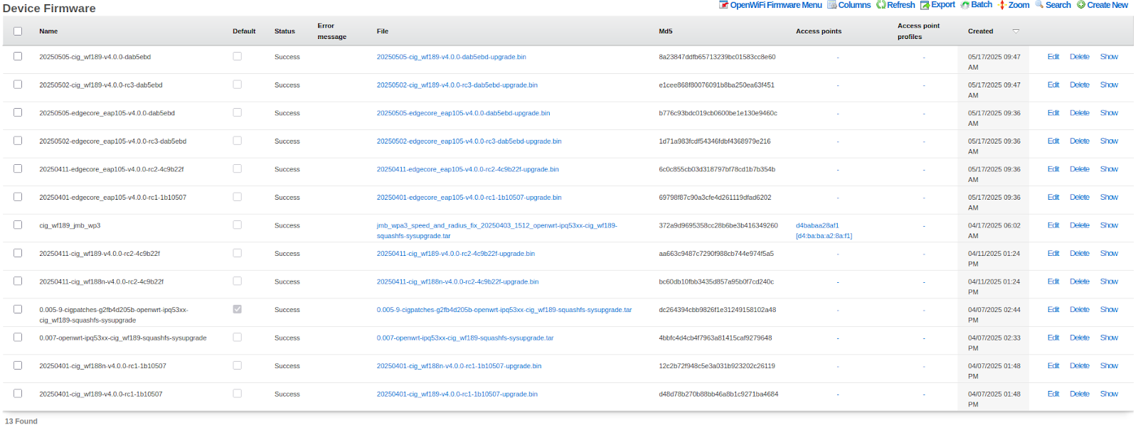
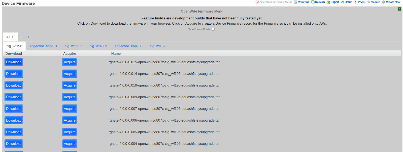
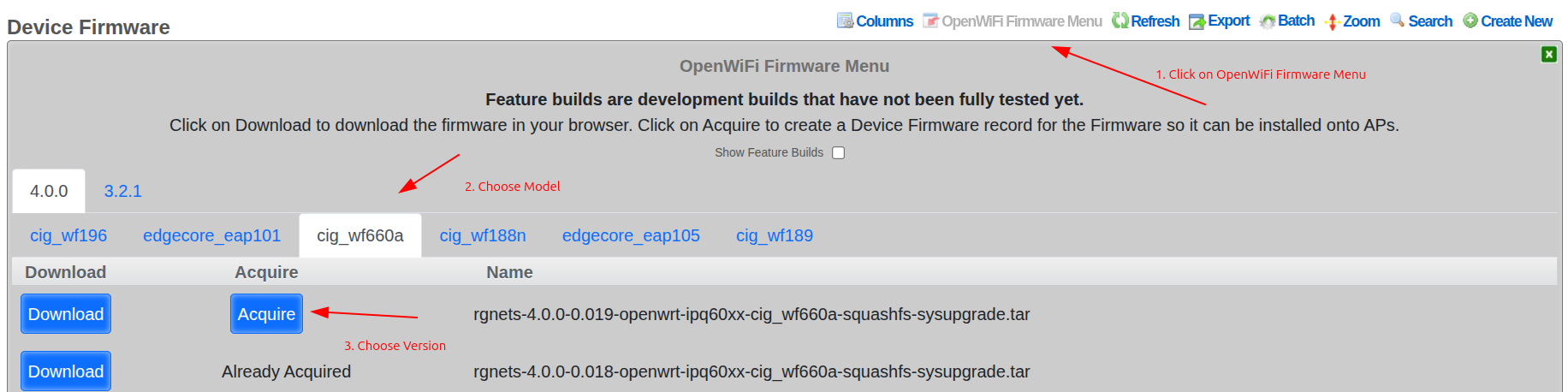
The rXg includes a built-in interface for easily acquiring the latest firmware. The Acquire button downloads it to the rXg for easy installation onto WAPs. The Download button downloads it to your PC.
Method A: Per-Device Firmware Assignment
- Navigate to Network >> Wireless >> Device Firmware
- Edit the target firmware record
- Select specific WAPs in the Access points field
- Click Update
This method provides selective upgrade capability for testing before wider rollout.

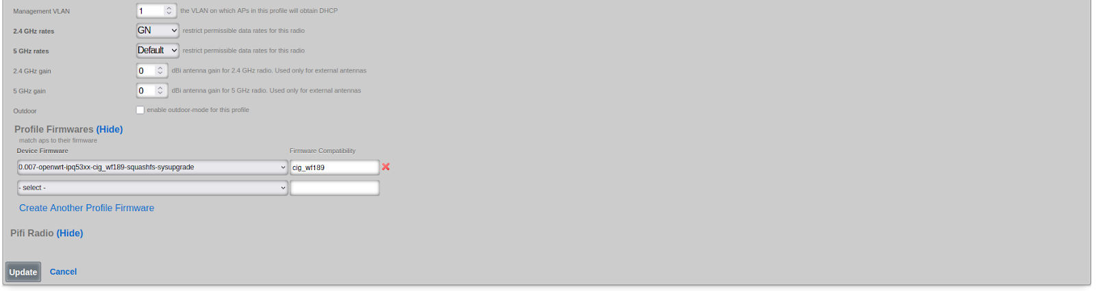
Method B: Profile-Based Firmware Assignment
- Navigate to Network >> Wireless >> Access Point Profiles
- Edit the target profile
- Under Profile Firmwares, select the target firmware
- Associate with specific device models (e.g.,
cig_wf189) - Click Update
This method rolls out firmware to all WAPs with matching hardware models in the profile.
Firmware Upgrade Behavior:
- The Sync Firmware button upgrades WAPs only if target version is higher
- The Upgrade Firmware button on individual WAPs forces upgrade regardless of version
- Firmware compatibility is tracked via a firmware_compatibility string
Cluster Configuration
When deploying OpenWiFi WSS in a multi-node rXg cluster, the system automatically distributes WAP connections across all available cluster nodes for improved performance and high availability.
Note: This section applies only to WSS deployments in clustered environments.
How Cluster Load Balancing Works
Endpoint Discovery and Persistence:
- Initial Bootstrap: On first connection, WAPs discover the cluster controller via DHCP option 224
- Endpoint Distribution: Once connected, the rXg sends a list of all active cluster nodes (
rxg_endpoints) in the state message - Persistent Storage: The WAP stores this endpoint list in
/root/rxg_endpoints.jsonfor future use
Load Distribution:
- On startup, WAPs load the persisted endpoint list and randomly select a cluster node to connect to
- This random selection naturally distributes WAP connections across all available nodes
- Each WAP independently makes its selection, resulting in balanced load distribution
Automatic Failover:
- If a WAP loses connection to its current node, it immediately tries the next endpoint in its list
- No exponential backoff occurs between trying different nodes
- Only after exhausting all available endpoints does the WAP wait before retrying
- This ensures rapid failover with minimal downtime
Example /root/rxg_endpoints.json:
[
  {
    "name": "rxg-node-01.example.com",
    "domain_name": "rxg-node-01.example.com"
  },
  {
    "name": "rxg-node-02.example.com",
    "domain_name": "rxg-node-02.example.com"
  }
]
Monitoring Node Distribution
The rXg provides real-time visibility into WAP distribution across cluster nodes through the Node Distribution dashboard widget.
Access: Navigate to Wireless Access Points, then click the "Node Distribution" button in the action bar.
The dashboard displays:
- Pie Chart: Visual representation of which WAPs are connected to which cluster nodes
- Summary Statistics: Total connected WAPs, active cluster nodes, and average WAPs per node
- Detailed Breakdown: Table showing WAP count and percentage per node
Technical Details:
- Connection tracking uses Redis to store the WAP-to-node mapping (
openwifi_ap_nodeshash) - Data is updated in real-time as WAPs connect and disconnect
- The dashboard auto-refreshes every 30 seconds to show current distribution
- This information helps operators verify load balancing effectiveness and identify potential issues
Benefits:
- High Availability: WAPs automatically failover to healthy nodes without operator intervention
- Load Distribution: Random selection ensures even distribution of WAP connections
- No Single Point of Failure: Any cluster node can serve as the WSS endpoint for any WAP
- Self-Healing: WAPs automatically return to optimal nodes as cluster health improves
- Visibility: Real-time monitoring of connection distribution across the cluster
Enabling Nodes for WSS Management
Each cluster node can be individually configured for WSS management participation using the Use for WSS Management boolean in the Cluster Node settings (System Cluster).
How It Works:
- When enabled, the node participates in the WSS management plane and accepts WAP connections
- When disabled, the node is excluded from the endpoint list sent to WAPs and will not accept new WSS connections
- This setting allows operators to designate specific nodes for WSS management while using other nodes for different purposes
Use Cases:
- Dedicated Management Nodes: Reserve specific nodes exclusively for WAP management in large clusters
- Maintenance Mode: Temporarily exclude a node from receiving new WAP connections during maintenance
- Capacity Planning: Gradually introduce new nodes into the management plane
- Resource Isolation: Separate management traffic from data plane or control plane operations
Configuration:
Navigate to System Cluster, edit a cluster node, and toggle the "Use for WSS Management" checkbox. Changes take effect on the next state message push to WAPs (typically within 60 seconds).
Important Notes:
- Disabling WSS management on a node does not disconnect currently connected WAPs immediately
- WAPs will naturally reconnect to other nodes during their next connection cycle or failover event
- At least one node must have WSS management enabled for the cluster to function properly
- The automatic rebalancing system only considers nodes with WSS management enabled
Automatic Load Rebalancing
In addition to initial load distribution, the rXg includes an automatic rebalancing system that continuously monitors and optimizes WAP distribution across cluster nodes to prevent overload conditions.
How Automatic Rebalancing Works:
The rebalancing job runs every minute and evaluates the current WAP distribution. It only triggers a rebalance when specific conditions are met:
Trigger Conditions:
- Minimum Threshold: The busiest node must have at least 100 WAPs connected
- Imbalance Detection: The difference between the most and least loaded nodes exceeds 15% of total WAPs (minimum 10 WAP difference)
- Target Health: The target node must be active and healthy and have WSS management enabled
Rebalancing Process:
When triggered, the system:
- Identifies Source and Target: Finds the most overloaded and least loaded WSS-capable nodes
- Calculates Move Count: Determines how many WAPs to move (2% of overloaded node's count, maximum 10 per run)
- Selects Candidate WAPs: Randomly selects WAPs from the overloaded node, excluding recently rebalanced WAPs
- Triggers Reconnection: Sends a state message with
intended_nodefield to selected WAPs - Prevents Ping-Ponging: Marks moved WAPs with a 10-minute cooldown to prevent oscillation
WAP Response to Rebalancing:
When a WAP receives a state message containing an intended_node different from its current connection:
- The Python WSS client detects the intended node in the state data
- The WAP immediately disconnects from its current node
- The intended node is prioritized in the reconnection attempt
- The WAP establishes a new connection to the specified node
Example Scenario:
Initial state:
  Node A: 150 WAPs
  Node B: 50 WAPs
  Total: 200 WAPs

Imbalance: 100 WAPs (50% difference)
Threshold: 30 WAPs (15% of 200)

Action: Move 3 WAPs from Node A to Node B (2% of 150)

Result:
  Node A: 147 WAPs
  Node B: 53 WAPs
Monitoring:
The Node Distribution dashboard displays a visual threshold indicator showing which nodes are above or below the rebalancing threshold:
- Green badge: Node is below threshold (normal operation)
- Amber badge: Node is at or above threshold (may trigger rebalancing)
Configuration:
The rebalancing threshold is currently set to 100 WAPs and is defined in the ClusterNode::WSS_REBALANCING_THRESHOLD constant. This value represents the minimum number of WAPs on the busiest node before automatic rebalancing will consider triggering.
Benefits:
- Prevents Overload: Automatically redistributes load before any single node becomes overwhelmed
- Gradual Convergence: Small, incremental moves (2% per run) prevent disruption while achieving balance over time
- Stability: Cooldown periods and thresholds prevent unnecessary WAP movement
- Zero Operator Intervention: Runs automatically in the background with no configuration required
- Graceful: WAPs reconnect cleanly using the same mechanism as normal failover
Technical Details:
- Job runs via ActiveJob queue:
RebalanceOpenwifiWssNodesJob - Execution frequency: Every 1 minute
- Maximum WAPs moved per run: 10
- Cooldown per WAP: 10 minutes
- Health check: Uses
is_activemethod to verify target node availability
Troubleshooting
This section covers common issues and recovery procedures for OpenWiFi WAPs.
Common Issues
Broken NTP on Prior-Configured WAPs
If the WAP is struggling to connect to the rXg's HTTPS interface, it may have a malfunctioning clock. This should be fixed during the firmware installation process, but in case it is not, here are two solutions.
Solutions:
- Factory Reset WAP
- Via SSH:
uci delete system.ntp.server
uci add_list system.ntp.server='time.google.com'
uci commit system
/etc/init.d/sysntpd restart
Client Experience Monitoring Not Running
If client experience pings are not appearing in telemetry, check the following:
Step 1: Verify Zone Configuration
- Navigate to Wireless >> Access Point Zones
- Edit the OpenWiFi WSS zone
- Ensure "Enable Client Experience Pings" is checked
- Ensure "Client Experience Ping Targets" contains valid domains or IP addresses (e.g., google.com, 8.8.8.8)
Step 2: Check WAP State
- Navigate to Wireless >> Access Points
- Find the WAP in question
- Check the test_vlan_id field in OpenWiFi -> Expected State Data
- If nil, monitoring will not run
Step 3: Verify PMS Room Assignment - Ensure the WAP is assigned to a PMS Room - Navigate to Wireless >> Access Points >> edit >> PMS Room field
Step 4: Check Account and VLAN Assignment - Navigate to the PMS Room (Users >> PMS Rooms) - Verify at least one Account is associated with the room - Check that the Account has a VLAN Tag Assignment - Verify the VLAN belongs to a tunnel pseudo interface (not a standard VLAN)
Step 5: Check Room Size - Count the number of WAPs assigned to the same PMS Room - If 25 or more WAPs share the room, monitoring is automatically disabled for DHCP pool protection
Step 6: Verify Tunnel Configuration - At least one WLAN must have tunneling configured - Navigate to Wireless >> WLANs >> edit WLAN >> Tunnel Type - Ensure tunnel destination is configured
Step 7: Check WAP Logs - SSH to the WAP and check logs for client experience monitor status - Look for messages like: - "Starting client experience monitor" - "No test VLAN ID configured in AP state" - "tunnel configuration not found" - "DHCP acquisition failed on test VLAN"
Using an rXg as an HTTP Virtual Host to L7 Proxy WAP <> rXg WSS Traffic
WAP -> WSS GET /cable -> HTTP Virtual Host rXg -> proxied request -> OW Controller rXg
This configuration is not supported and will prevent OpenWiFi WAPs from authenticating properly.
The mTLS authentication fails because the intermediary rXg's HTTP proxy terminates the TLS connection and does not forward the client certificate to the controlling rXg. OpenWiFi WAPs require bidirectional certificate verification, and the controlling rXg cannot verify the WAP's identity without access to the client certificate.
Solution: Use Direct Routing Establish network routing that allows OpenWiFi WAPs to communicate directly with the controlling rXg without passing through an intermediary proxy. This can be achieved through proper network segmentation, VPN tunnels, or dedicated routing rules that bypass the proxy rXg entirely for OpenWiFi WSS traffic while maintaining the proxy for other services. Consider using policy-based routing or VLAN separation to achieve this configuration.
Certificate Problems
Certificate issues can prevent WAPs from establishing WSS connections to the rXg. Use the following steps to diagnose and resolve certificate-related problems.
Symptoms: - WAPs show "Offline" status and never transition to "Online" - WAP LED shows cyan blink (EST server unreachable) - Adoption process stalls after firmware installation - WSS connection fails with TLS/SSL errors
Step 1: Verify Certificate Authority Status
Navigate to System >> Certificates >> Certificate Authorities and check:
- CA exists and is associated with the WLAN Controller
- CA has not expired (check the Not After date)
- CA Common Name matches the rXg hostname
Via CLI:
# Check CA certificate details
openssl x509 -in /etc/ssl/rxg/ca.crt -text -noout | grep -E "Subject:|Not After"

# Verify CA is not expired
openssl x509 -in /etc/ssl/rxg/ca.crt -checkend 0
If the CA has expired, create a new CA and update the WLAN Controller association.
Step 2: Verify EST Server Configuration
Navigate to System >> DHCP >> Options and verify:
- An EST Server Option exists
- The option is associated with the correct DHCP pool(s)
- The Certificate Authority field references a valid CA
The EST Server Option is required for WAPs to obtain certificates during the adoption process.
Step 3: Check WLAN Controller Certificate Association
Navigate to Network >> Wireless >> WLAN Controllers and verify:
- The controller has a Certificate Authority selected
- The selected CA matches the one used for EST Server
Step 4: Verify WAP Certificate (via SSH)
If you can SSH to the WAP, check its certificate status:
# Check if certificate exists
ls -la /etc/ucentral/cert.pem /etc/ucentral/key.pem

# Verify certificate details
openssl x509 -in /etc/ucentral/cert.pem -text -noout | grep -E "Subject:|Issuer:|Not After"

# Verify certificate is signed by the rXg CA
openssl verify -CAfile /etc/ucentral/ca.pem /etc/ucentral/cert.pem
Example Output - Working Certificate:
$ openssl x509 -in /etc/ucentral/cert.pem -text -noout | grep -E "Subject:|Issuer:|Not After"
        Issuer: C = US, ST = California, L = San Francisco, CN = rxg.example.com, emailAddress = [email protected]
        Not After : Dec 25 12:00:00 2034 GMT
        Subject: CN = d4:ba:ba:a1:41:d0

$ openssl verify -CAfile /etc/ucentral/ca.pem /etc/ucentral/cert.pem
/etc/ucentral/cert.pem: OK
In a working configuration:
- Issuer matches the rXg's Certificate Authority CN
- Not After date is in the future (certificate not expired)
- Subject contains the WAP's MAC address
- Verification returns OK
Example Output - Expired Certificate:
$ openssl x509 -in /etc/ucentral/cert.pem -text -noout | grep -E "Subject:|Issuer:|Not After"
        Issuer: C = US, ST = California, L = San Francisco, CN = rxg.example.com, emailAddress = [email protected]
        Not After : Jan 15 08:30:00 2024 GMT
        Subject: CN = d4:ba:ba:a1:41:d0

$ openssl verify -CAfile /etc/ucentral/ca.pem /etc/ucentral/cert.pem
C = US, ST = California, L = San Francisco, CN = rxg.example.com, emailAddress = [email protected]
error 10 at 1 depth lookup: certificate has expired
error /etc/ucentral/cert.pem: verification failed
Example Output - CA Mismatch:
$ openssl x509 -in /etc/ucentral/cert.pem -text -noout | grep -E "Subject:|Issuer:|Not After"
        Issuer: C = US, ST = California, L = San Francisco, CN = old-rxg.example.com, emailAddress = [email protected]
        Not After : Dec 25 12:00:00 2034 GMT
        Subject: CN = d4:ba:ba:a1:41:d0

$ openssl verify -CAfile /etc/ucentral/ca.pem /etc/ucentral/cert.pem
error 20 at 0 depth lookup: unable to get local issuer certificate
error /etc/ucentral/cert.pem: verification failed
In this case, the WAP certificate was signed by a different CA (old-rxg.example.com) than the one currently configured. Factory reset the WAP to re-enroll with the correct CA.
Example Output - Missing Certificate:
$ ls -la /etc/ucentral/cert.pem /etc/ucentral/key.pem
ls: /etc/ucentral/cert.pem: No such file or directory
ls: /etc/ucentral/key.pem: No such file or directory
The WAP never completed EST enrollment. Check EST Server configuration and re-import the WAP.
Step 5: Test mTLS Connection
From the WAP, test the WSS connection manually:
# Test mTLS handshake to rXg
openssl s_client -connect <rxg-hostname>:443 \
  -cert /etc/ucentral/cert.pem \
  -key /etc/ucentral/key.pem \
  -CAfile /etc/ucentral/ca.pem
Look for:
- Verify return code: 0 (ok) - Certificate chain is valid
- Verify return code: 10 - Certificate has expired
- Verify return code: 18 - Self-signed certificate (CA mismatch)
- Verify return code: 21 - Unable to verify first certificate
Step 6: Check rXg Logs
On the rXg, check for certificate-related errors:
# Check AnyCable logs for WSS connection issues
tail -f /var/log/anycable.log | grep -i cert

# Check nginx logs for TLS errors
tail -f /var/log/nginx/error.log | grep -i ssl
Common Fixes:
| Problem | Solution |
|---|---|
| Expired CA | Create new CA, update WLAN Controller, re-adopt WAPs |
| Missing EST Server Option | Create EST Server Option in DHCP settings |
| CA mismatch | Ensure WLAN Controller and EST Server use same CA |
| WAP certificate expired | Factory reset WAP and re-adopt |
| Clock skew on WAP | Fix NTP (see "Broken NTP" section above) |
Re-issuing WAP Certificates:
If a WAP's certificate is invalid or expired:
- Factory reset the WAP:
firstboot -yrvia SSH, or hold reset button - Wait for WAP to reboot and acquire DHCP
- Re-import the WAP from the WLAN Controllers page
- Approve the WAP in Access Points
The adoption process will automatically provision a new certificate via EST.
WAP Recovery
This section covers hardware-level recovery for completely unresponsive OpenWiFi WAPs using U-Boot TFTP recovery. Use this procedure when the WAP has corrupted firmware, failed upgrades, or is otherwise unrecoverable through normal means.
When to Use This Procedure: - WAP is stuck in a boot loop - Firmware upgrade failed and WAP won't boot - WAP is completely unresponsive to network commands - Normal factory reset does not resolve the issue
Required Materials
| Item | Description |
|---|---|
| USB-to-Serial Cable | CP2102 USB to TTL RS232 (3.3V) - Example |
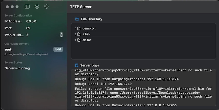
| TFTP Server | Software running on your laptop (e.g., Tftpd64, Fast TFTP) |
| Ethernet Cable | Direct connection between laptop and WAP LAN port |
| PoE Injector | Power source for WAP via WAN port |
| Terminal Software | PuTTY, screen, minicom, or similar |
Required Firmware Files:
| File | Purpose |
|---|---|
openwrt-ipq53xx-cig_wf189-initramfs-kernel.bin |
Temporary boot image loaded via TFTP |
rgnets-X.X.X-openwrt-ipq53xx-cig_wf189-squashfs-sysupgrade.tar |
Permanent firmware flashed to WAP |
Note: Replace
cig_wf189with your WAP model andX.X.Xwith the appropriate firmware version.

Phase 1: Hardware Setup
Step 1: Identify the Serial Port
Locate the serial console header on your WAP. The pinout varies by model.
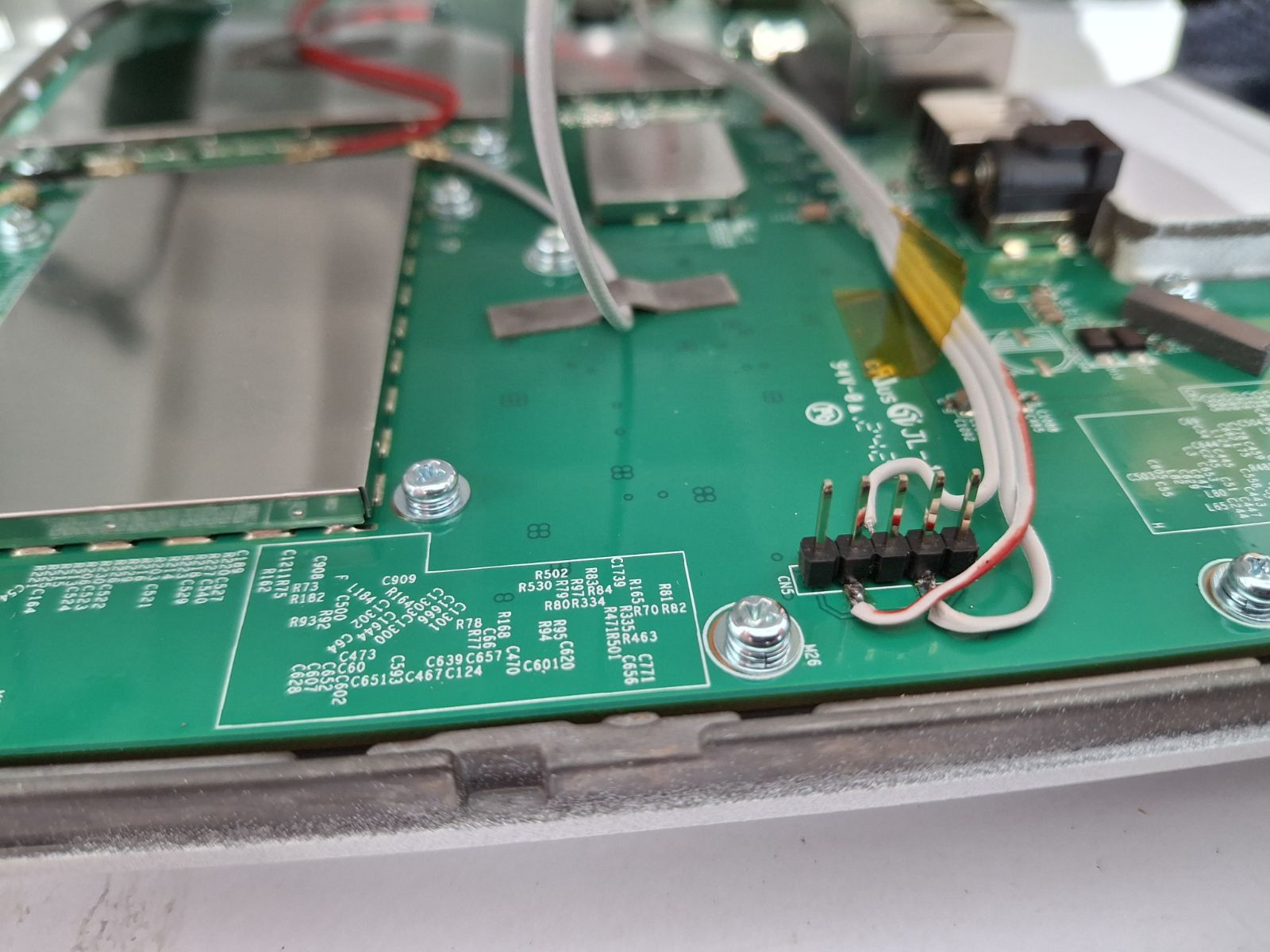
Step 2: Connect the Serial Cable
Connect only 3 wires from the USB-to-serial cable to the WAP:
| Cable Wire | Color (typical) | WAP Pin |
|---|---|---|
| TX | White | Pin 2 |
| GND | Black | Pin 3 |
| RX | Green | Pin 4 |
Warning: Do not connect the red (VCC/5V) wire - it can damage the WAP.
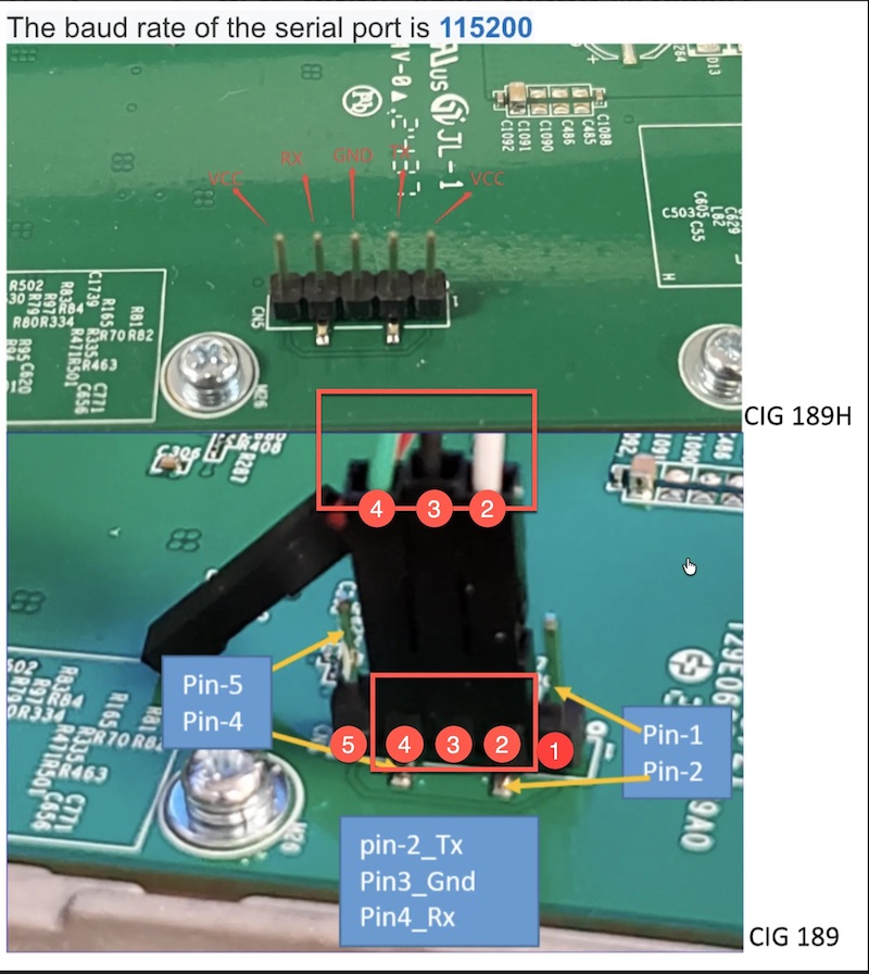
Step 3: Configure Terminal Software
Open your terminal application with these settings:
| Setting | Value |
|---|---|
| Baud Rate | 115200 |
| Data Bits | 8 |
| Parity | None |
| Stop Bits | 1 |
| Flow Control | None |
Step 4: Configure Network
- Connect WAP WAN port to PoE injector (power source)
- Connect WAP LAN port to your laptop's Ethernet port
- Configure your laptop's IP address:
- IP:
192.168.1.10 - Subnet:
255.255.255.0 - Gateway: (leave blank)
- IP:
Step 5: Start TFTP Server
- Launch your TFTP server application
- Set the TFTP root directory to the folder containing the firmware files
- Ensure the server is listening on
192.168.1.10
Phase 2: Boot into U-Boot
Step 1: Enter U-Boot Console
- With serial terminal open, power on the WAP
- Immediately and repeatedly press Enter or Space (try alternating)
- You must interrupt the boot within 2-3 seconds
Expected Output - Successful Interrupt:
U-Boot 2016.01 (Feb 15 2023 - 12:00:00 +0000)

...
Hit any key to stop autoboot:  0
IPQ9574#
The IPQ9574# prompt (or similar) indicates you are in U-Boot. If you see Linux boot messages scrolling, power cycle and try again.
Step 2: Configure U-Boot Networking
At the U-Boot prompt, enter these commands:
setenv ipaddr 192.168.1.1
setenv serverip 192.168.1.10
Step 3: Verify Connectivity
ping 192.168.1.10
Expected Output - Success:
Using eth0 device
host 192.168.1.10 is alive
If the ping fails, check your Ethernet cable and laptop IP configuration.
Phase 3: Load Temporary Boot Image
Step 1: Download initramfs Image via TFTP
tftpboot openwrt-ipq53xx-cig_wf189-initramfs-kernel.bin
Expected Output:
Using eth0 device
TFTP from server 192.168.1.10; our IP address is 192.168.1.1
Filename 'openwrt-ipq53xx-cig_wf189-initramfs-kernel.bin'.
Load address: 0x44000000
Loading: #################################################################
         #################################################################
         #####################
         3.2 MiB/s
done
Bytes transferred = 7864320 (780000 hex)
Step 2: Boot the Image
bootm
The WAP will boot into a temporary Linux environment. Wait for the boot process to complete (approximately 30-60 seconds).
Expected Output - Boot Complete:
...
[    5.432100] NET: Registered protocol family 10
[    5.567890] Segment Routing with IPv6

BusyBox v1.35.0 () built-in shell (ash)

  _______                     ________        __
 |       |.-----.-----.-----.|  |  |  |.----.|  |_
 |   -   ||  _  |  -__|     ||  |  |  ||   _||   _|
 |_______||   __|_____|__|__||________||__|  |____|
          |__| W I R E L E S S   F R E E D O M
 -----------------------------------------------------

root@OpenWrt:/#
Step 3: Log In
If prompted, log in with:
- Username: root
- Password: openwifi (or blank on some builds)
Important: This is a temporary RAM-based system. If you reboot now, you will need to repeat Phase 2 and 3.
Phase 4: Flash Permanent Firmware
Step 1: Start HTTP Server on Laptop
On your laptop, open a terminal and navigate to the folder containing the sysupgrade file:
cd /path/to/firmware/files
python3 -m http.server 80
Expected Output:
Serving HTTP on 0.0.0.0 port 80 (http://0.0.0.0:80/) ...
Step 2: Download Firmware to WAP
On the WAP serial console:
cd /tmp
wget http://192.168.1.10/rgnets-4.0.0-0.027-openwrt-ipq53xx-cig_wf189-squashfs-sysupgrade.tar
Expected Output:
Connecting to 192.168.1.10 (192.168.1.10:80)
saving to 'rgnets-4.0.0-0.027-openwrt-ipq53xx-cig_wf189-squashfs-sysupgrade.tar'
rgnets-4.0.0-0.027 100% |*******************************| 12.5M  0:00:02 ETA
'rgnets-4.0.0-0.027-openwrt-ipq53xx-cig_wf189-squashfs-sysupgrade.tar' saved
Step 3: Flash the Firmware
sysupgrade -n rgnets-4.0.0-0.027-openwrt-ipq53xx-cig_wf189-squashfs-sysupgrade.tar
The -n flag performs a clean flash without preserving settings.
Expected Output:
Commencing upgrade. Closing all shell sessions.
Sending TERM to remaining processes ...
Sending KILL to remaining processes ...
Switching to ramdisk...
Performing system upgrade...
Unlocking firmware ...
Writing from <stdin> to firmware ...
Upgrade completed
Rebooting system...
Phase 5: Verify Recovery
- Wait for Reboot: Allow 2-3 minutes for the WAP to fully boot
- Check LED Status: Look for the "disco ball" pattern (alternating colors) indicating the WAP is ready for adoption
- Verify Network: From your laptop, ping the WAP:
ping 192.168.1.1
- Re-adopt WAP: Use the rXg's WAP discovery to import and approve the device
Recovery Troubleshooting
TFTP Download Fails - Check TFTP server is running and accessible - Verify Ethernet connections - Ensure firmware files are in TFTP root
Cannot Enter U-Boot - Try Space or Ctrl+C instead of Enter - Press keys immediately after power-on - Some models require holding reset button during power-on
Boot Failure After Recovery - Verify correct firmware for WAP model - Check firmware compatibility string - Try different firmware version
Post-Recovery
- Initial Setup: WAP boots with factory defaults at
192.168.1.1 - Re-adoption: Use rXg's WAP discovery to re-adopt the device
- Verification: Confirm WSS connection and configuration sync
Alternative Methods
Web Recovery (Limited Models)
1. Hold reset button while powering on (10-15 seconds)
2. Connect via Ethernet to 192.168.1.1
3. Upload firmware through web interface
Serial Console Benefits - Full visibility into boot process - Error message monitoring - Maximum recovery control
Technical Reference
This section provides technical details for advanced configuration and troubleshooting.
Public Key Infrastructure (PKI)
- A Local Certificate Authority (CA) must be created on the rXg and associated with the OpenWiFi WLAN Controller.
- All WAPs must receive a certificate signed by this CA, which they use to authenticate themselves to the rXg via mTLS.
DNS and Network Considerations
- Public IP: Ideally, the rXg has a public IP address that the WAP can resolve via public DNS.
- NAT Scenario: OpenWiFi WAPs have rebind protection and will not accept RFC1918 addresses from DNS. If the rXg is behind NAT, it will attempt to manage the
/etc/hostsfile on the WAP via SSH so the WAP can resolve the rXg's private IP.
Key Files and Directories
On the WAP:
- /certificates: Works with /etc/ucentral to persist certificate data.
- /etc/ucentral/: Main configuration directory for Ucentral.
- /usr/share/ucentral/: Contains .uc files for commands like wifiscan.
- /etc/hosts: Managed by the rXg for DNS resolution in NAT scenarios.
- /etc/config/: Key OpenWRT Configuration files pertaining to DHCP, DNS, and a lot more.
- /etc/config-shadow/: OpenWiFi extension of /etc/config
Command-Line Interface (CLI)
WAP Commands:
- firstboot -yr: Performs a factory reset on the WAP.
rXg Commands:
- anycab: Used to view WAP-to-rXg activity in AnyCable on the rXg.
Onboarding
- OpenWiFi WAPs must be discovered by a scan and approved by the rXg to be onboarded.
- Approval can be either manual or automatic. This is set by an Auto Approve boolean in the WlanDevice.
SDK Technical Reference
This section provides technical details specific to the SDK (OWGW) deployment.
OWGW Architecture
The OpenWiFi Gateway controller SDK is deployed as Docker containers inside an Ubuntu VM. The VM is pre-built by RG Nets with: - OWGW software from the TIP community - Additional functionality for rXg discovery and integration - The VM expects the rXg to be its IP gateway
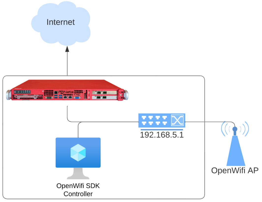
OWGW Adoption Workflow
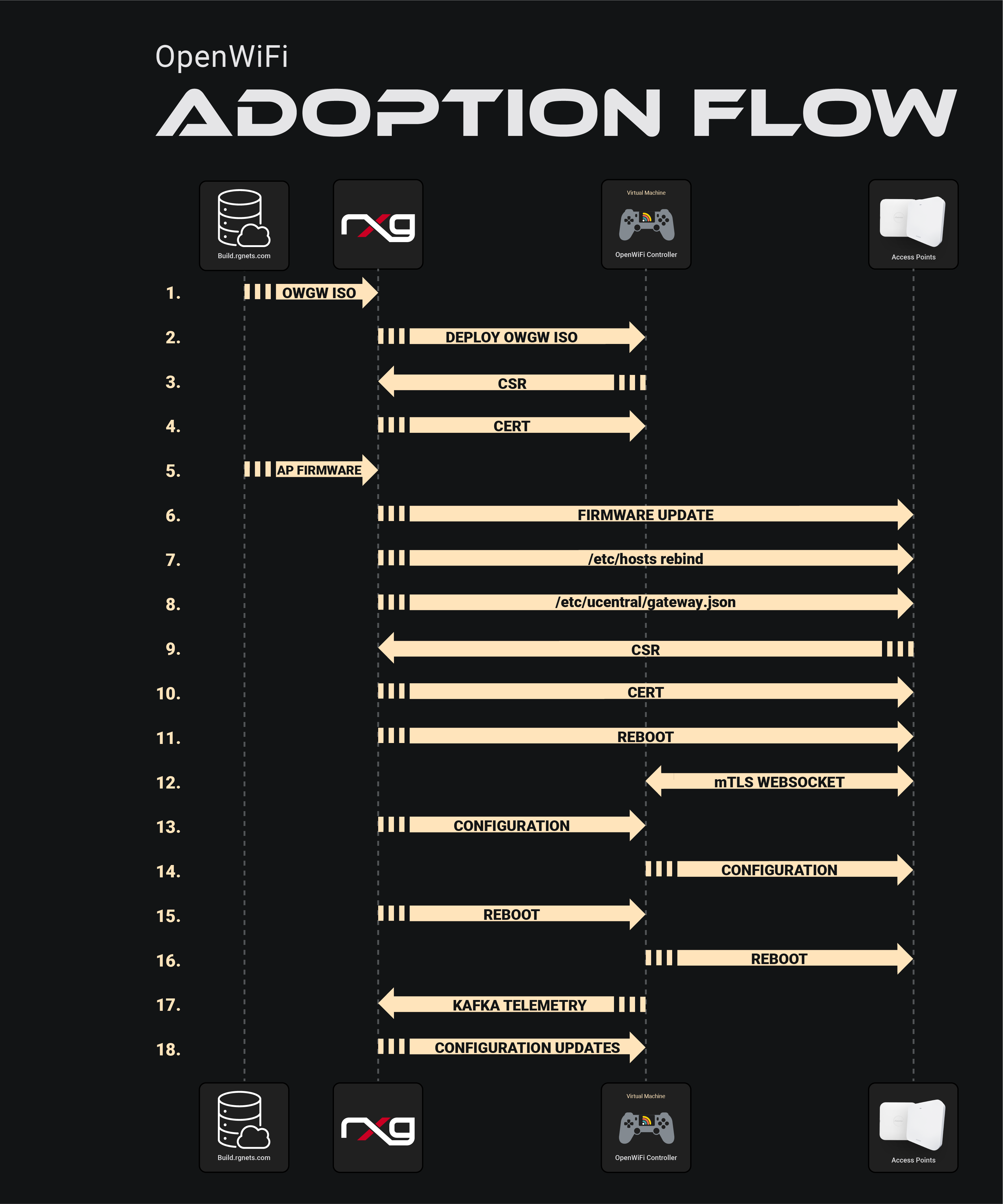
The adoption workflow illustrates the 18-step process between the build server, rXg controller, OWGW, and WAPs during device onboarding, including: - OWGW deployment - Certificate signing requests (CSR) - Certificate distribution - Firmware updates - Configuration management - mTLS WebSocket connection establishment
DNS Considerations (SDK)
- OpenWiFi WAPs will not accept private IPs in DNS responses (rebind protection)
- The rXg manages
/etc/hostson WAPs for DNS resolution in NAT scenarios - Default FQDN:
openwifi.wlan.local - The OWGW reconfigures its DNS server to use its gateway
OWGW Management
All OWGW functions are managed via systemctl:
# Restart OWGW services
sudo systemctl restart docker-compose-openwifi
This command re-runs controller acquisition, fixes DNS, and restarts Docker containers.
Key Directories:
- /work_dir/wlan-cloud-ucentral-deploy/docker-compose - Docker compose files
- /work_dir/wlan-cloud-ucentral-deploy/docker-compose/certs - Certificates
- /usr/local/bin - Management scripts
- /etc/resolv.conf - DNS configuration
WAP Key Files (SDK Mode)
/certificates- Works with/etc/ucentralto persist certificate data/etc/ucentral/- Main Ucentral configuration directory/etc/ucentral/gateway.json- Controller discovery configuration/etc/hosts- DNS rebinding for NAT'd deployments
Testing WSS Connection:
openssl s_client -connect openwifi.wlan.local:15002 \
  -cert /etc/ucentral/cert.pem \
  -key /etc/ucentral/key.pem
Success is indicated by Post-Handshake New Session Ticket arrived: in the output.
rXg Integration
- The OWGW exposes Kafka on a port for rXg telemetry collection
- Use
tfltelcommand on the rXg to view telemetry traffic - If monitoring is enabled, Kafka telemetry creates WAP radios but not wireless clients or WAPs
SSH Access
Cloud-init allows adding users during first VM launch:
- Default user: openwifi-admin
- SSH keypair must be configured in the template
Network Topology
WAPs do not need to be in the same L2 domain as the OWGW. They can operate on different network segments as long as IP routing is available.


