Data Processing Units (DPU)
Overview
Data Processing Units (DPUs) are specialized System-on-Chip (SoC) processors designed to offload and accelerate data center infrastructure tasks from the main CPU. The rXg platform provides comprehensive support for NVIDIA BlueField DPUs, enabling hardware-accelerated packet processing, advanced network virtualization, and integrated security services that dramatically improve system performance and efficiency.
DPU Architecture and Capabilities
Modern DPUs represent a convergence of multiple processing technologies that work together to deliver unprecedented network performance and functionality. At the heart of each DPU lies an ARM-based control plane that operates independently from the host system, providing a complete computing environment for network services and management functions.
The ARM processor subsystem varies by generation, with BlueField-3 featuring multi-core ARM Cortex-A78 processors while BlueField-2 utilizes Cortex-A72 cores. These processors run a full Linux operating system, typically Ubuntu 22.04 LTS, providing a familiar environment for deploying standard Linux applications and services. The dedicated memory subsystem ranges from 8GB to 32GB of DDR4 memory, ensuring sufficient resources for complex network functions without impacting host system memory. The independent boot process, managed through UEFI firmware, allows the DPU to initialize and begin processing even before the host operating system loads, enabling critical network services to be available immediately upon system power-on.
Hardware acceleration engines form the core of the DPU's performance advantages. These specialized processors implement programmable packet processing pipelines that can be configured for specific network functions without requiring software changes. The encryption and decryption engines support industry-standard algorithms including AES-256 and ChaCha20, processing encrypted traffic at line rate without CPU intervention. Compression and decompression acceleration enables efficient data transfer and storage, particularly valuable for backup and replication scenarios. Pattern matching and deep packet inspection capabilities allow real-time content analysis for security and application identification purposes. These acceleration engines work in concert to enable complex network function virtualization (NFV) deployments that would otherwise require dedicated hardware appliances.
The high-speed network interfaces provide the physical connectivity required for modern data center networks. DPUs support a range of speeds from 25Gbps to 200Gbps Ethernet, with flexible configuration options that allow administrators to match interface speeds to their specific requirements. For example, a single 200Gbps interface can be split into two 100Gbps interfaces or four 25Gbps interfaces, providing deployment flexibility without hardware changes. Advanced traffic shaping and quality of service capabilities ensure that critical traffic receives appropriate prioritization, while hardware-based VLAN tagging, tunneling protocols, and overlay network support enable complex network virtualization schemes. The entire packet forwarding path is optimized for low latency, achieving sub-microsecond processing times for most operations.
PCIe host integration provides the critical link between the DPU and the host system. The PCIe interface supports both Gen3 x16 and Gen4 configurations, with the specific requirements depending on the DPU model and desired performance characteristics. Direct memory access (DMA) capabilities allow the DPU to transfer data directly to and from host memory without CPU involvement, significantly reducing overhead for high-bandwidth applications. Shared memory regions facilitate efficient communication between host applications and DPU services, enabling tight integration while maintaining isolation boundaries. The support for virtual functions (VF) and sub-functions (SF) enables advanced virtualization scenarios where multiple virtual machines or containers can have dedicated network resources managed by the DPU.
rXg DPU Integration Benefits
The integration of DPUs into the rXg platform delivers transformative benefits across performance, security, and operational domains. These advantages stem from the fundamental architectural shift of moving infrastructure functions from general-purpose CPUs to purpose-built processing units optimized for network and security workloads.
Performance enhancement represents the most immediately visible benefit of DPU deployment. By offloading network processing tasks to the DPU, host CPU utilization can be reduced by up to 80%, freeing these valuable compute resources for application workloads. Hardware-accelerated packet processing delivers throughput improvements of 10 to 15 times compared to software-only solutions, enabling organizations to handle growing traffic volumes without proportional increases in hardware investment. The parallel processing architecture of DPUs allows multiple network and security functions to execute simultaneously without the context switching overhead inherent in CPU-based processing. Furthermore, the dedicated resources within the DPU eliminate performance contention between network functions and applications, ensuring predictable performance even under peak load conditions.
Advanced network services that would traditionally require dedicated appliances can now be consolidated onto the DPU infrastructure. High-performance firewalling with stateful connection tracking processes millions of concurrent sessions while maintaining line-rate throughput. IPsec VPN acceleration leverages hardware encryption engines to establish secure tunnels without the CPU overhead typically associated with cryptographic operations. Support for high-performance L2GRE and other tunneling mechanisms enables sophisticated overlay networks for multi-tenancy and workload mobility. Load balancing and traffic distribution functions operate at wire speed, intelligently directing traffic based on application requirements and server availability. Network address translation (NAT) performs address mapping at line rate, supporting complex networking topologies without performance penalties. Advanced routing protocols benefit from hardware-based Forwarding Information Base (FIB) support, enabling rapid route convergence and lookup operations.
Security improvements extend beyond performance to include architectural advantages that enhance the overall security posture. The isolated security processing environment within the DPU ensures that security functions operate independently of the host operating system, protecting against compromise even if the host is breached. Hardware-based cryptographic operations provide both performance and security benefits, as cryptographic keys and operations remain within the secure confines of the DPU hardware. Zero-trust network micro-segmentation becomes practical at scale, with the DPU enforcing granular security policies between workloads without impacting application performance. Real-time threat detection and mitigation capabilities leverage the DPU's position in the data path to identify and respond to security events as they occur. Encrypted storage and secure boot capabilities ensure that both data at rest and the DPU firmware itself remain protected against tampering.
Operational efficiency gains simplify the deployment and management of complex network infrastructure. The centralized management through the rXg interface provides a single pane of glass for configuring and monitoring all DPU resources, eliminating the need for separate management tools. Automated provisioning and configuration reduce deployment time from hours to minutes, with the rXg platform handling the complex orchestration required to initialize and configure DPU resources. Real-time monitoring and telemetry provide unprecedented visibility into network operations, with detailed metrics collected directly from the hardware acceleration engines. Simplified maintenance and updates ensure that DPU firmware and software remain current without requiring manual intervention or service disruption. Integration with existing rXg policy frameworks means that DPU capabilities can be leveraged immediately within established operational procedures, without requiring staff retraining or process changes.
Supported Hardware
The rXg platform provides comprehensive support for NVIDIA BlueField-2 and BlueField-3 DPU families across multiple SKUs and configurations. Each generation offers distinct capabilities and performance characteristics optimized for different deployment scenarios.
BlueField-2 Family
BlueField-2 DPUs represent the second generation of NVIDIA data processing units, offering a mature platform with proven reliability and extensive field deployment experience. These DPUs have been widely adopted across data center environments, providing a stable foundation for network acceleration and offload capabilities.
The core processing power of BlueField-2 comes from eight ARM Cortex-A72 processor cores operating at 2.5GHz, delivering substantial compute capacity for control plane operations and network services. The ConnectX-6 Dx network controller provides the foundation for high-speed networking, implementing advanced features in hardware to achieve consistent performance regardless of packet size or traffic patterns. Hardware acceleration extends across networking, security, and storage domains, enabling comprehensive infrastructure offload. RDMA over Converged Ethernet (RoCE) support enables ultra-low latency communication for storage and high-performance computing applications, while SR-IOV capabilities supporting up to 127 virtual functions per port provide the flexibility needed for modern virtualized environments.
Memory and storage configurations in BlueField-2 DPUs are optimized for embedded network applications. The LPDDR4 memory subsystem ranges from 8GB to 16GB depending on the SKU, providing sufficient capacity for running complex network functions while maintaining power efficiency. The integrated eMMC storage hosts the operating system and applications, eliminating the need for external storage devices and simplifying deployment. Hardware memory protection and encryption features ensure that sensitive data remains secure, even in multi-tenant environments where isolation is critical.
Network interface flexibility allows BlueField-2 DPUs to adapt to various deployment scenarios. Single-port configurations support up to 100GbE or even 200GbE on select SKUs, ideal for high-bandwidth applications requiring maximum throughput on a single connection. Dual-port options provide 50GbE or 25GbE per port, enabling redundant connections or traffic segregation between different network segments. Port splitting capabilities allow administrators to divide high-speed interfaces into multiple lower-speed connections, providing deployment flexibility without requiring different hardware SKUs.
The BlueField-2 product line includes several popular SKUs, each optimized for specific use cases. The MBF2H332A provides dual 25GbE ports with 16GB memory, making it ideal for edge deployments requiring redundancy. The MBF2H516A offers a single 100GbE port with 16GB memory, perfect for high-throughput applications. The MBF2M516A provides the same specifications in an OCP 3.0 form factor, designed for Open Compute Platform deployments. The BFM2515A represents a special case, physically containing dual-port hardware that requires cross flashing to unlock the second port, providing a cost-effective upgrade path for organizations whose needs evolve over time.
BlueField-3 Family
BlueField-3 represents the latest generation of NVIDIA DPUs, delivering substantial performance improvements and expanded capabilities that address the demands of modern data center infrastructure. This generation introduces architectural enhancements that significantly increase processing power while improving efficiency.
The processing capabilities of BlueField-3 center around sixteen ARM Cortex-A78 cores operating at 2.6GHz, doubling the core count from BlueField-2 while also moving to a more advanced architecture. The ConnectX-7 network controller introduces new capabilities including enhanced programmability, improved packet processing efficiency, and support for emerging network protocols. The enhanced hardware acceleration engines provide greater throughput for cryptographic operations, compression, and pattern matching, enabling more complex security and networking functions to be offloaded from the host CPU. Despite the increased performance, BlueField-3 incorporates improved power efficiency features and thermal management capabilities that optimize performance per watt. Advanced telemetry and monitoring features provide detailed insights into system operation, enabling proactive management and optimization.
Memory and storage options in BlueField-3 reflect the increased demands of modern network functions. DDR4 memory configurations range from 16GB to 32GB, providing ample capacity for running multiple concurrent services and maintaining large connection state tables. NVMe storage options deliver the high-performance I/O required for logging, packet capture, and application data, with significantly improved throughput compared to the eMMC storage used in previous generations. Enhanced security features including secure boot, encrypted memory, and hardware root of trust provide defense-in-depth protection for critical infrastructure.
Network interface configurations in BlueField-3 support the highest speeds available in modern data centers. Single-port 400GbE configurations provide maximum bandwidth for backbone connections, while dual-port 200GbE options offer redundancy at ultra-high speeds. For environments requiring more ports at lower speeds, 100GbE dual-port and quad-port 25GbE configurations provide flexibility to match specific deployment requirements. Advanced traffic management and quality of service capabilities ensure that critical traffic receives appropriate treatment even under congestion conditions.
Power requirements for BlueField-3 reflect its increased capabilities, with power consumption exceeding 150W under full load. This necessitates dual PCIe power connectors to ensure stable power delivery, and deployments must account for this additional power infrastructure. Enhanced cooling becomes critical for maintaining optimal performance, as thermal throttling will reduce performance if adequate cooling is not provided. Integration with IPMI-based power management allows remote monitoring and control of power states, facilitating data center automation and energy efficiency initiatives.
Hardware Compatibility Requirements
Successful DPU deployment requires careful attention to system compatibility across multiple dimensions. The rXg platform requires a minimum version of 16.011 for initial DPU support, though version 16.100 or later is recommended for access to all features and optimizations. This version requirement ensures that all necessary kernel modules, drivers, and management software are present and properly integrated.
PCIe slot requirements vary based on the specific DPU model and desired performance characteristics. While a Gen3 x16 slot represents the minimum requirement, Gen4 x8 or x16 slots provide improved bandwidth that can be beneficial for high-throughput applications. The system must allocate at least 8GB of RAM specifically for DPU operations, in addition to the base memory requirements for the rXg platform itself. Proper cooling and airflow are essential, as DPUs generate significant heat that must be dissipated to maintain stable operation.
Power and thermal considerations differ significantly between DPU generations. BlueField-2 DPUs consume a maximum of 75W and require only a single PCIe power connector, making them suitable for systems with limited power budgets. BlueField-3 DPUs consume 150W or more and require dual PCIe power connectors, necessitating more robust power infrastructure. Both generations benefit from ambient temperature monitoring and support thermal throttling to protect against overheating, though maintaining ambient temperatures below 35C is recommended for optimal performance.
Network cabling requirements depend on the interface speeds and distances involved in the deployment. High-quality Direct Attach Copper (DAC) cables provide cost-effective connectivity for short distances, typically up to 5 meters for 100GbE and 3 meters for higher speeds. Fiber optic transceivers enable longer distance connections and are required for distances exceeding DAC cable capabilities. Proper impedance matching and signal integrity are critical for achieving rated speeds, particularly at 200GbE and above.
Verification and Compatibility Checking
Before deployment, verify hardware compatibility:
# Check PCIe slot capabilities
pciconf -lv | grep -A 5 -B 5 mellanox

# Verify power delivery
dmidecode -t slot | grep -A 10 "PCIe"

# Check thermal monitoring
sysctl hw.acpi.thermal

# Verify rXg version
cat /etc/rxg_release
rXg Version Features: - 16.011: Initial DPU support with basic management capabilities - 16.050: Enhanced VPP integration and monitoring improvements - 16.100: Advanced cross flashing and recovery options - 16.200+: Full feature parity and automated provisioning
For the most current list of tested and validated DPU models, including firmware compatibility matrices and known limitations, please refer to the rXg Hardware Compatibility Guide at https://support.rgnets.com/knowledge/104.
Cross Flashing
Cross flashing refers to the process of configuring a DPU with different firmware characteristics than its default configuration. This advanced procedure enables unlocking additional ports, resolving MAC address conflicts, and optimizing virtualization settings for specific deployment scenarios.
Warning: Cross flashing modifies low-level firmware settings and should only be performed by experienced administrators. Incorrect configuration may render the DPU inoperable and require RMA.
Prerequisites for Cross Flashing
Before beginning the cross flashing process, ensure all prerequisites are met to minimize risk and enable recovery if issues occur.
Physical and Remote Access Requirements:
Console access to both the host system and DPU is essential for monitoring the cross flashing process and troubleshooting any issues that arise. Ensure IPMI or similar out-of-band management is configured and tested, as power cycling is often required to complete firmware changes. The command ipmitool power status should return the current power state successfully before proceeding.
Configuration Documentation: Document the current firmware configuration comprehensively before making any changes: ```bash
Save current configuration to file
mlxconfig -d pci0:1:0:0 q > dpu_config_backup.txt
Record current firmware version
mstflint -d pci0:1:0:0 q > firmware_version_backup.txt ```
Firmware and Tool Requirements: Ensure you have the necessary firmware files and tools: - Target firmware binary (.bin file) for the desired PSID - Mellanox Firmware Tools (MFT) version 4.32.0 or later - Known-good BFB image for recovery (e.g., bf-bundle-3.0.0-135_25.04_ubuntu-22.04_prod.bfb) - Access to NVIDIA firmware download portal for obtaining firmware files
Firmware Download Sources: Official firmware can be obtained from: ```bash
Example for MT_0000000561 PSID (dual-port 100GbE)
Extract the firmware
unzip fw-BlueField-2-rel-24_43_1014-MBF2M516A-CEEO_Ax_Bx.bin.zip ```
Network Isolation: Schedule cross flashing during a maintenance window to avoid service disruption. Ensure that critical services can continue operating without the DPU during the cross flashing process, which typically takes 30-60 minutes including verification.
Recovery Preparation: Prepare recovery procedures before starting: - Have physical access to the server for manual intervention if needed - Document the original PSID and firmware version - Test RSHIM connectivity before beginning - Ensure you have administrator credentials for both host and DPU systems
PSID Modification for Port Unlocking
Some DPU models ship with firmware that restricts the number of available ports. The BFM2515A, for example, physically contains two ports but firmware limits access to only one.
Identifying Cards Requiring PSID Change
Check your card's current PSID:
bash
mlxconfig -d pci0:1:0:0 q | grep PSID
For BFM2515A cards showing MT_0000000750, change to MT_0000000561 to unlock the second port.
PSID Change Procedure
Verify Current Configuration:
bash
mlxconfig -d pci0:1:0:0 q PSID
Apply PSID Change:
bash
mlxconfig -d pci0:1:0:0 -y s PSID=MT_0000000561
Confirm Change:
bash
mlxconfig -d pci0:1:0:0 q PSID
Power Cycle Required: A full system power cycle is mandatory for PSID changes to take effect.
Real-World PSID Change Example
The following example demonstrates converting a BlueField-2 from single-port 200GbE to dual-port 100GbE configuration:
Initial Hardware State:
Model: NVIDIA BlueField-2 Ethernet DPU 200GbE
Part Number: BF2M515A
PSID: MT_0000000750
Description: BlueField-2 E-Series DPU 200GbE Single-Port QSFP56
Target Configuration:
Model: BlueField-2 E-Series DPU 100GbE Dual-Port
Part Number: MBF2M516A-CEEO_Ax_Bx
PSID: MT_0000000561
Description: BlueField-2 E-Series DPU 100GbE Dual-Port QSFP56
Step 1 - Query Current Firmware:
bash
sudo mstflint -d 0000:03:00.0 q
Output shows:
Image type:            FS4
FW Version:            24.31.2006
Base GUID:             b8cef6030075621c
Base MAC:              b8cef675621c
PSID:                  MT_0000000750
Step 2 - Flash New Firmware with PSID Change:
bash
sudo mstflint -d 0000:03:00.0 -i fw-BlueField-2-rel-24_43_1014-MBF2M516A-CEEO_Ax_Bx.bin \
  -allow_psid_change burn
When prompted about PSID change from MT_0000000750 to MT_0000000561, confirm with 'y'.
Step 3 - Verify After Reboot:
bash
lspci | grep BlueField
Expected output showing dual ports:
03:00.0 Ethernet controller: Mellanox Technologies MT42822 BlueField-2
03:00.1 Ethernet controller: Mellanox Technologies MT42822 BlueField-2
Common PSID Configurations
Different PSIDs unlock specific hardware capabilities:
MT_0000000750 - Single-Port 200GbE configuration with crypto disabled, suitable for maximum bandwidth on a single connection.
MT_0000000561 - Dual-Port 100GbE configuration with crypto enabled, recommended for redundancy and security requirements.
MT_0000000376 - Dual-Port 100GbE/EDR/HDR100 VPI configuration.
MT_0000000765 - Dual-Port 25GbE configuration with integrated BMC and 32GB DDR, ideal for edge deployments.
MAC Address Conflict Resolution
After cross flashing, DPUs may experience MAC address conflicts between interfaces. This occurs when the out-of-band (OOB) management interface shares the same MAC address as a data plane interface.
Detecting MAC Address Conflicts
- Connect to DPU: Use the rXg
sshdpucommand to access the DPU ARM OS - Check Interface Status: Verify expected interfaces are present (p0, p1, oob_net0)
- Run Conflict Detection:
bash
ip a | awk '/^[0-9]+: (p0|p1|oob_net0):/{f=1} f&&/link\/ether/{print $2; f=0}' | sort -u | awk 'END{if(NR==3) print " OK"; else print " Conflict"}'
MAC Address Conflict Resolution Procedure
When conflicts are detected:
Mount EFI Variables Filesystem:
bash
mount | grep efivars
If not mounted:bash mount -t efivarfs none /sys/firmware/efi/efivarsRemove Immutability Protection:
bash
chattr -i /sys/firmware/efi/efivars/OobMacAddr-8be4df61-93ca-11d2-aa0d-00e098032b8c
Calculate and Set New OOB MAC: The new OOB MAC is derived by adding 8 to the last byte of the p0 interface MAC address:
bash
printf "\x07\x00\x00\x00$(ip link show p0 | awk '/link\/ether/{split($2,m,":"); printf "\\x%s\\x%s\\x%s\\x%s\\x%s\\x%02x", m[1],m[2],m[3],m[4],m[5], ("0x"m[6])+8}')" > /sys/firmware/efi/efivars/OobMacAddr-8be4df61-93ca-11d2-aa0d-00e098032b8c
Reboot DPU: A DPU reboot is required to apply MAC address changes
Verify Resolution: Re-run the conflict detection script to confirm resolution
DPU Mode Configuration via Host
The rXg supports configuring DPU virtualization settings directly from the FreeBSD host using mlxconfig, eliminating the need for manual UEFI configuration.
Identifying DPU PCI Address
Locate the DPU device on the PCI bus:
bash
pciconf -lv | grep 0x15b3
Example output showing device at pci0:1:0:0:
mlx5_core0@pci0:1:0:0: class=0x020000 rev=0x01 hdr=0x00 vendor=0x15b3 device=0xa2d6
mlx5_core1@pci0:1:0:1: class=0x020000 rev=0x01 hdr=0x00 vendor=0x15b3 device=0xa2d6
none1@pci0:1:0:2: class=0x080100 rev=0x01 hdr=0x00 vendor=0x15b3 device=0xc2d3
BlueField-2 Virtualization Configuration
For BlueField-2 DPUs, apply the following configuration as root:
bash
mlxconfig -d pci0:1:0:0 -y s \
  INTERNAL_CPU_MODEL=1 \
  INTERNAL_CPU_PAGE_SUPPLIER=0 \
  INTERNAL_CPU_ESWITCH_MANAGER=0 \
  INTERNAL_CPU_IB_VPORT0=0 \
  INTERNAL_CPU_OFFLOAD_ENGINE=0 \
  VIRTIO_NET_EMULATION_ENABLE=1 \
  VIRTIO_NET_EMULATION_NUM_PF=4 \
  VIRTIO_NET_EMULATION_NUM_VF=126 \
  VIRTIO_NET_EMULATION_NUM_MSIX=64 \
  PCI_SWITCH_EMULATION_ENABLE=0 \
  PCI_SWITCH_EMULATION_NUM_PORT=0 \
  PER_PF_NUM_SF=1 \
  PF_TOTAL_SF=512 \
  PF_BAR2_ENABLE=0 \
  PF_SF_BAR_SIZE=8 \
  NUM_VF_MSIX=0 \
  SRIOV_EN=1
BlueField-3 Virtualization Configuration
For BlueField-3 DPUs, use this configuration:
bash
mlxconfig -d pci0:1:0:0 -y s \
  INTERNAL_CPU_MODEL=1 \
  EXP_ROM_UEFI_ARM_ENABLE=1 \
  VIRTIO_NET_EMULATION_ENABLE=1 \
  VIRTIO_NET_EMULATION_NUM_PF=4 \
  VIRTIO_NET_EMULATION_NUM_VF=126 \
  VIRTIO_NET_EMULATION_NUM_MSIX=64 \
  PCI_SWITCH_EMULATION_ENABLE=0 \
  PCI_SWITCH_EMULATION_NUM_PORT=0 \
  PER_PF_NUM_SF=1 \
  PF_TOTAL_SF=512 \
  PF_BAR2_ENABLE=0 \
  PF_SF_BAR_SIZE=8 \
  NUM_VF_MSIX=0 \
  SRIOV_EN=1
Configuration Parameters Reference
| Parameter | Description | Purpose |
|---|---|---|
| INTERNAL_CPU_MODEL | Enables embedded ARM SoC as DPU controller | Required for DPU mode operation |
| INTERNAL_CPU_PAGE_SUPPLIER | Controls page allocation between host and embedded CPU | Set to 0 for host-managed memory |
| INTERNAL_CPU_ESWITCH_MANAGER | Manages eSwitch control plane location | Set to 0 for host-based management |
| INTERNAL_CPU_IB_VPORT0 | Controls InfiniBand vport0 management | Set to 0 to disable for Ethernet-only (the mode supported by rXg) |
| INTERNAL_CPU_OFFLOAD_ENGINE | Enables offload between host and ARM | Set to 0 for simplified configuration |
| EXP_ROM_UEFI_ARM_ENABLE | Enables UEFI expansion ROM for ARM boot | Required on BF3 for embedded boot |
| VIRTIO_NET_EMULATION_ENABLE | Enables firmware-level virtio-net emulation | Core virtualization functionality |
| VIRTIO_NET_EMULATION_NUM_PF | Number of virtio Physical Functions | Controls PF exposure to host |
| VIRTIO_NET_EMULATION_NUM_VF | Number of virtio Virtual Functions | Total VFs across all PFs |
| VIRTIO_NET_EMULATION_NUM_MSIX | MSI-X vectors per virtio function | Interrupt handling capacity |
| PER_PF_NUM_SF | Sub-Functions per Physical Function | Advanced virtualization features |
| PF_TOTAL_SF | Total available Sub-Functions | System-wide SF allocation |
| SRIOV_EN | Enables SR-IOV exposure to host | Required for VF functionality |
Verifying Applied Configuration
After applying configuration changes, verify the settings:
bash
mlxconfig -d pci0:1:0:0 q | egrep "VIRTIO_NET_EMULATION|PCI_SWITCH_EMULATION|PF_|NUM_VF_MSIX|SRIOV|PER_PF_NUM_SF|INTERNAL_CPU|EXP_ROM"
Post-Configuration Procedures
Power Cycle Requirements
All cross flashing operations require a complete power cycle to take effect:
bash
ipmitool power cycle
Important: A warm reboot is insufficient. The system must be fully powered off and restarted for firmware changes to initialize properly.
Firmware Image Updates
After successful cross flashing and power cycle:
- Navigate to DPU Software Management: Network DPU DPU Software
- Upload Latest BFB: Use the most recent stable image (e.g.,
bf-bundle-3.1.0-76_25.07_ubuntu-22.04_prod.bfb) - Perform Firmware Upgrade: Follow standard firmware update procedures
- Final Power Cycle: Execute one additional power cycle after firmware installation
Validation Steps
After completing cross flashing, perform comprehensive verification to ensure all interfaces and services are operational.
Step 1 - Verify DPU Detection in rXg: Navigate to Network DPU DPU Devices and confirm the DPU appears with correct status.
Step 2 - Confirm Network Interface Availability:
bash
sudo lshw -class network -businfo
Expected output after successful dual-port configuration: ```
Bus info Device Class Description
pci@0000:03:00.0 p0 network MT42822 BlueField-2 integrated ConnectX-6 Dx pci@0000:03:00.1 p1 network MT42822 BlueField-2 integrated ConnectX-6 Dx virtio@1 tmfifo_net0 network Ethernet interface oob_net0 network Ethernet interface ```
Step 3 - Verify Firmware Details:
bash
sudo mlxfwmanager
Confirm the output shows: - Correct Part Number (e.g., MBF2M516A-CEEO_Ax_Bx for dual-port) - Updated PSID (e.g., MT_0000000561) - Description indicating dual-port configuration
Step 4 - Test RSHIM Communication:
bash
cat /dev/rshim0/misc
This should return JSON telemetry data confirming the RSHIM interface is operational.
Step 5 - Verify Management Connectivity:
Test SSH access to the DPU:
bash
ssh [email protected]
Step 6 - Check VPP Service Status:
Once connected to the DPU:
bash
sudo systemctl status vpp
Step 7 - Monitor System Logs:
Review logs for any errors or warnings:
bash
grep -i "dpu\|rshim\|mlx" /var/log/messages | tail -20
Recovery Procedures
If cross flashing results in an unresponsive DPU:
- Attempt Software Reset: Use Network DPU DPU Devices Software Reset
- Force Firmware Reflash: Upload a known-good BFB image and force upgrade
- Power Cycle Sequence: Perform multiple power cycles with 30-second intervals
- RSHIM Recovery: Check
/dev/rshim*/miscfor device status and reset capabilities
Cross Flashing Best Practices
Cross flashing success depends on following established best practices that minimize risk and ensure recoverability. Always document all configuration changes and original settings before beginning any cross flashing operation, including the original PSID, firmware version, and any custom configurations. Test cross flashing procedures in staging environments before attempting production deployments, as this allows validation of the process and identification of potential issues without risking critical infrastructure.
Implement comprehensive monitoring and alerting for DPU status changes during and after cross flashing operations. This includes setting up notifications for RSHIM connectivity loss, firmware version mismatches, and interface state changes. Maintain detailed rollback plans that include known-good firmware images, configuration backups, and step-by-step recovery procedures. Version control for firmware files and configuration parameters ensures that successful configurations can be replicated and problematic changes can be quickly identified.
Cross Flashing Troubleshooting Guide
When cross flashing encounters issues, systematic troubleshooting helps identify and resolve problems quickly.
Firmware Flash Fails to Start:
If mstflint returns errors when attempting to flash:
```bash
Verify device is not in use
lsof | grep mlx
Reset device to clear any locks
sudo mlxfwreset -d 0000:03:00.0 reset
Retry with verbose output
sudo mstflint -d 0000:03:00.0 -i firmware.bin -allow_psid_change burn -v ```
RSHIM Interface Not Available After Flash: ```bash
Restart RSHIM service
sudo systemctl stop rshim sudo systemctl start rshim
Check for device presence
ls -la /dev/rshim*/
If still unavailable, perform cold reset
sudo mlxfwreset -d 0000:03:00.0 -l 1 -t 4 r ```
DPU Stuck in Boot Loop: Access the console to diagnose boot issues: ```bash
Connect to console
sudo screen /dev/rshim0/console 115200
Monitor boot messages for errors
Common issues include:
- Corrupted filesystem: Requires BFB reflash
- Network configuration conflicts: Boot to recovery mode
- Driver version mismatches: Update host drivers
**Verifying Successful PSID Change**:
```bash
# From host system
sudo mstflint -d 0000:03:00.0 query full | grep PSID

# From DPU after boot
sudo devlink dev info

# Check both ports are visible (for dual-port configs)
ip link show | grep "^[0-9]" | grep -E "p0|p1"
Initial Setup
The initial setup process for DPU integration with rXg involves hardware installation, automatic discovery, and configuration validation. This section provides comprehensive guidance for successfully deploying DPUs in production environments.
Prerequisites
Before beginning DPU configuration, ensure all prerequisites are met to avoid installation issues and performance degradation.
Physical Installation Requirements
The physical installation of a DPU requires careful attention to several critical factors. The PCIe slot must be properly prepared, starting with verification of slot compatibility. While Gen3 x16 is the minimum requirement, Gen4 x8 or x16 slots are recommended for optimal performance. The slot should be clean and free from debris, with proper grounding and static protection in place. BIOS or UEFI settings must be configured to disable PCIe power saving features and set maximum payload sizes. Additionally, Above 4G Decoding must be enabled in the BIOS to ensure proper BAR mapping for the DPU's memory regions.
Power connectivity differs significantly between DPU generations. BlueField-2 cards require only a single 6-pin or 8-pin PCIe power connector, while BlueField-3 cards demand dual 8-pin PCIe power connectors, both of which must be connected for proper operation. The system's power supply should provide at least 750W capacity when hosting BlueField-3 DPUs, with dedicated PSU rails recommended to avoid power fluctuations that could impact performance or stability. Power monitoring tools should be installed to track consumption patterns and identify potential issues before they affect production workloads.
Thermal management represents one of the most critical aspects of DPU deployment. These high-performance processors generate significant heat that must be effectively dissipated to maintain optimal operation. The ambient temperature should be maintained below 35C, with a minimum of 200 CFM airflow directed across the DPU heatsink. When installing multiple DPUs, maintain at least a one-slot gap between cards to ensure adequate airflow. Temperature monitoring sensors should be deployed if not already integrated into the system, and thermal throttling policies should be configured in the BIOS to protect against overheating conditions.
Network cabling requires careful selection based on interface speeds and distances. For Direct Attach Copper (DAC) cables, maximum lengths are 5 meters for 100GbE connections and 3 meters for 200GbE interfaces. When using fiber optic transceivers, compatibility with the DPU firmware must be verified before deployment. All cables should be clearly labeled to distinguish between management and data plane connections, and cable integrity should be tested before production deployment to avoid connectivity issues.
System Requirements
The rXg platform requires specific configuration to support DPU operations effectively. The minimum rXg version for DPU support is 16.011, though version 16.100 or later is recommended for access to the full feature set including advanced monitoring and automated provisioning capabilities. Each DPU requires 8GB of dedicated RAM in addition to the base rXg memory requirements, ensuring sufficient resources for packet processing and management operations. The system should maintain at least 10GB of free storage space for BFB firmware images and operational logs. A multi-core processor is recommended to handle the management operations without impacting data plane performance.
Operating system configuration involves several components working together. The kernel must have both cuse.ko and mlx5_core.ko modules loaded for DPU communication and management. The RSHIM user-space daemon must be installed and running to provide the management interface between the host and DPU. Firewall rules need to be configured to permit TMFIFO communication on the management network, typically using the 192.168.100.0/24 subnet. The SSH key infrastructure must be properly established to enable secure passwordless authentication between the rXg and DPU operating systems.
Network architecture planning should be completed before beginning installation. This includes defining the management network topology, particularly the TMFIFO addressing scheme that will be used for host-to-DPU communication. Data plane interface assignments should be documented, mapping physical DPU ports to their intended network segments. VLAN and tunneling requirements must be established based on the network design, and QoS and traffic prioritization policies should be defined to ensure critical traffic receives appropriate handling through the DPU acceleration engines.
Automatic Discovery
The rXg platform implements a sophisticated automatic discovery mechanism that significantly simplifies DPU deployment. Upon system boot, the platform initiates a comprehensive discovery process that begins with PCIe enumeration to detect all installed DPU devices. This enumeration identifies NVIDIA/Mellanox vendor IDs and determines the specific DPU model, generation, and capabilities based on the device ID and subsystem information.
Once a DPU is detected, the system automatically loads the required kernel modules, primarily cuse.ko, which provides the character device in userspace functionality necessary for RSHIM communication. The platform then installs and configures the rshim-user-space-rs daemon, which serves as the primary management interface between the host system and the DPU's embedded ARM processor. This daemon handles all low-level communication protocols and provides abstraction layers for higher-level management operations.
The TMFIFO (Tile Management FIFO) network interface creation represents a critical step in establishing host-to-DPU communication. The system automatically creates a virtual network interface, typically named tmfifo_net0 for the first DPU, which provides IP-based connectivity over the PCIe bus. This interface operates independently of the DPU's physical network ports and remains available even when data plane interfaces are misconfigured or offline. The default configuration assigns 192.168.100.1 to the host interface and 192.168.100.2 to the DPU, though these addresses can be modified if needed.
Security configuration occurs automatically through the generation of 4096-bit RSA SSH keys specifically for DPU communication. These keys are stored at /root/.ssh/dpu_id_rsa and are distinct from other system SSH keys to maintain security isolation. The public key is automatically deployed to the DPU's authorized_keys file, enabling passwordless authentication for management operations. If the DPU already contains existing keys from a previous installation, the system will attempt to update them while preserving any custom configurations that may have been applied.
The discovery process also includes capability detection, where the system queries the DPU to determine supported features such as VPP compatibility, available memory, firmware version, and hardware acceleration capabilities. This information is stored in the rXg database and used to optimize subsequent configuration and management operations. The entire discovery process typically completes within 30-60 seconds per DPU, depending on the firmware state and system load.
Manual Configuration
While automatic discovery handles most deployment scenarios, manual configuration may occasionally be necessary for specialized environments or when recovering from configuration issues. Manual configuration should generally be avoided to prevent misconfiguration, but understanding the process is valuable for troubleshooting and advanced deployments.
To begin manual configuration, navigate to Network DPU DPU Devices in the rXg interface. The system will display any auto-discovered DPUs with a status of "missing," indicating they have been detected but not yet configured. Clicking on a DPU entry opens the configuration interface where several parameters can be customized.
The Name field should contain a descriptive identifier for the DPU that clearly indicates its role or location in the network infrastructure. Examples include "Production DPU 1" or "Edge-Router-DPU-A". This naming convention becomes particularly important in multi-DPU deployments where clear identification is essential for management and troubleshooting.
The TMFIFO Address field specifies the management IP address assigned to the DPU side of the TMFIFO interface. While the default of 192.168.100.2 works for single-DPU systems, environments with multiple DPUs require unique addresses for each device. The system automatically manages the host-side addressing to correspond with the configured DPU addresses, maintaining the .1 and .2 relationship within each subnet.
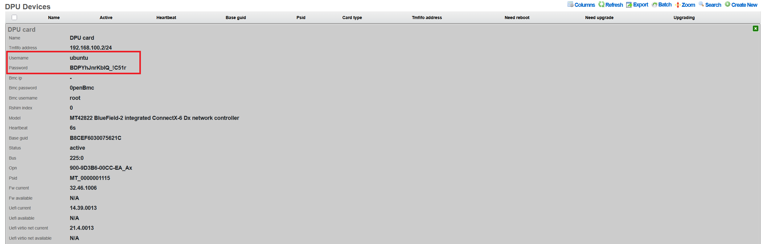
Authentication credentials consist of the Username and Password fields for the DPU operating system. The default username is "ubuntu" for all NVIDIA-provided firmware images. When the Password field is left blank, the system generates a cryptographically secure password of at least 16 characters, combining uppercase and lowercase letters, numbers, and special characters. This auto-generated password is stored securely and can only be viewed through the Show action after initial configuration. Alternatively, administrators can specify a custom password, though this should meet complexity requirements to maintain security.
For DPUs equipped with baseboard management controllers, the BMC Username, BMC Password, and BMC IP fields provide out-of-band management capabilities. The default BMC credentials are typically "root" and "0penBmc" respectively, though these should be changed after initial deployment for security reasons. The BMC IP address must be on a separate network from the TMFIFO interface and should be accessible from the rXg management network.
After entering all required configuration parameters, clicking Create saves the configuration and initiates the connection process. The system immediately attempts to establish communication with the DPU using the provided credentials and begins deploying the necessary management components. Success is indicated by the status changing from "missing" to "active" within approximately 30 seconds. If the connection fails, detailed error messages in the system log help identify whether the issue relates to network connectivity, authentication, or DPU firmware state.
Cluster Environments
DPU deployment in clustered rXg environments requires special consideration to ensure proper node affinity, failover behavior, and management isolation. The rXg clustering architecture automatically handles most aspects of DPU integration, but understanding the underlying mechanisms helps optimize performance and troubleshooting.
When a DPU is installed in a cluster node, the system automatically associates it with that specific node through PCIe bus enumeration and persistent device mapping. This association ensures that DPU resources remain tied to their physical host even during cluster reconfiguration or node maintenance. The automatic naming convention incorporates the cluster node prefix, such as "node1-dpu0" or "node2-dpu1", providing immediate visual identification of the DPU's physical location within the cluster infrastructure.
Management traffic isolation represents a critical security and reliability feature in clustered deployments. Each node maintains its own TMFIFO network segment for DPU communication, preventing management traffic from traversing the cluster interconnect. This isolation ensures that DPU management operations continue to function even if the cluster network experiences issues. The TMFIFO interfaces use non-overlapping IP ranges, with each node allocated a unique /24 subnet from the 192.168.x.0 private address space.
Failover scenarios in clustered environments are handled through state synchronization rather than live migration. When a node fails, its DPU resources become unavailable until the node is restored. However, the cluster maintains a synchronized copy of the DPU configuration in the distributed database, allowing rapid reconfiguration when the node returns to service. Critical network services configured on DPUs should be deployed in active-active or active-passive pairs across multiple nodes to ensure continuity during node failures.
The cluster coordination mechanism ensures that DPU firmware updates and configuration changes are properly sequenced across nodes. When updating DPU firmware in a cluster, the system automatically implements a rolling update strategy, upgrading one node's DPUs at a time to maintain service availability. This process includes automatic traffic draining from DPUs scheduled for update, firmware application with verification, and gradual traffic restoration after successful update completion.
Password Management
Default Credentials
The rXg uses the following default credentials:
DPU Operating System:
- Username: ubuntu
- Password: Auto-generated 16+ character secure password
The password is displayed only in the 'Show' action output, as shown below:
Changing Passwords
DPU OS Password
To change the DPU operating system password:
- Navigate to Network DPU DPU Devices
- Click Edit on the target DPU
- Enter new password in the Password field
- Click Update
The password change is applied immediately via the TMFIFO management interface. The system: - Validates SSH connectivity before applying changes - Updates both shadow file and cloud-init configuration - Maintains password through firmware updates
Password Recovery
If the DPU password is lost or forgotten, password recovery requires a complete DPU reflash:
- Navigate to Network DPU DPU Devices
- Click Upgrade on the affected DPU
- Select any available BFB firmware package (even the same version)
- Ensure Reboot After Upgrade is checked
- Click Submit Upgrade
The reflash process will: - Reset the DPU to factory defaults - Generate a new auto-generated password - Re-apply rXg SSH keys - Restore network configuration - The new password will be visible in the DPU Show action
Note: This process takes 15-30 minutes and requires a host system reboot.
After rXg Factory Reset
Important: If DPUs were previously configured with custom passwords and the rXg is factory reset, you must either: - Know the existing DPU passwords to reconfigure them - Perform a firmware reflash to reset DPU passwords (see Password Recovery above)
When the rXg is factory defaulted, DPU passwords must be reconfigured, since the DPU is not reflashed and the previous configured password remains on the DPU itself.
- Auto-discovered DPUs: The system will detect DPUs with status "missing"
- Navigate to Network DPU DPU Devices
- For each DPU, click Edit and set the password recorded from the DPU before the rXg was factory defaulted.
- Click Update to apply
The system will:
- Generate new SSH keys at /root/.ssh/dpu_id_rsa
- Deploy keys to all configured DPUs
- Validate connectivity before confirming
Password Security
The rXg implements several security measures: - Passwords are never displayed in the UI after initial entry - Export operations exclude password fields - Generated passwords use cryptographically secure random selection - Passwords include alphanumeric and special characters (!_-) - Minimum length of 16 characters for auto-generated passwords - SHA-512 hashing for password storage on DPU
SSH Key Management
The system automatically manages SSH keys for passwordless authentication:
- RSA 4096-bit keys generated at /root/.ssh/dpu_id_rsa
- Public keys automatically deployed to DPUs
- Legacy key migration supported from /root/.ssh/id_rsa
- Keys persist through firmware updates
Firmware Updates
Understanding BFB Files
BlueField Boot (BFB) files contain: - DPU operating system (Ubuntu-based) - Device firmware and drivers - Hardware initialization code - Network configuration templates
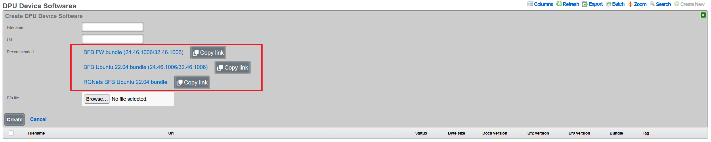
Uploading BFB Files
- Navigate to Network DPU DPU Software
- Click Create New
Configure the software package:
- Name: Descriptive name (e.g., "BlueField-2 v24.46.1006")
- Version: Firmware version number
- BFB File: Click Choose File and select the .bfb file
- Metadata: Optional JSON metadata for tracking
- Description: Optional description of changes
Click Create to upload
Note: BFB files are typically 1-2GB. Upload may take several minutes. Note that rXg also provides links to integrated DPU images with all rXg-specific extensions, which are recommended for production deployments.
Performing Firmware Updates
- Navigate to Network DPU DPU Devices
- Click Upgrade on the target DPU
- Select the uploaded BFB software package
Configure upgrade options:
- Reboot After Upgrade: Automatically reboot host system
- Review current vs. available firmware versions
Click Submit Upgrade
Upgrade Process
The firmware upgrade process: 1. Validates current DPU status (not already upgrading) 2. Writes BFB image via RSHIM boot interface 3. Monitors upgrade progress through log messages 4. Updates configuration (passwords, network settings) 5. Verifies "DPU is ready" status 6. Optionally reboots host system
Duration: Typical upgrade takes 15-30 minutes, and includes the recommended optional host system reboot to properly apply all the firmware patches.
Viewing Upgrade History
To view past upgrades: 1. Navigate to Network DPU DPU Devices 2. Click Upgrade History on the target DPU 3. Review: - Timestamp of each upgrade - BFB filename used - Duration of upgrade - Log messages from process - Any errors encountered
Network Configuration
TMFIFO Interface
The TMFIFO (Tile Management FIFO) provides the primary management channel:
- Created automatically as tmfifo_net[N] where N is the RSHIM index
- Default network: 192.168.100.0/24
- Host IP: 192.168.100.1
- DPU IP: 192.168.100.2 (for the first DPU in the system)
Configuring TMFIFO Network
To modify the TMFIFO network:
- Navigate to Network DPU DPU Devices
- Click Edit on the target DPU
- Update TMFIFO Address field
- Click Update
The system automatically: - Updates host interface configuration - Reconfigures DPU via netplan - Maintains connectivity during transition - Validates no IP conflicts exist
NOTE: the TMFIFO network address change is not recommended.
Network Isolation
The TMFIFO network architecture provides complete isolation between management and production traffic, ensuring that administrative operations never impact data plane performance. This isolation is achieved through the use of PCIe transport for all management communications, eliminating any dependency on external network infrastructure. The management traffic flows entirely within the server chassis, using the PCIe bus as a secure, high-speed transport mechanism that cannot be accessed from outside the host system. This design ensures that DPU management remains available even during network outages or misconfigurations. The data plane interfaces operate independently, processing production traffic without any awareness of the management channel. Host firewall rules provide an additional layer of protection, restricting access to the TMFIFO interfaces to authorized management processes only.
DPU Data Interfaces
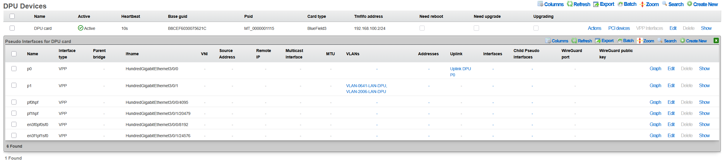
Physical network interfaces connected to the DPU undergo a sophisticated abstraction process to enable high-performance packet processing. These interfaces initially appear as PCI devices enumerated under the DPU's PCIe bridge, maintaining their hardware characteristics while being managed by the DPU's embedded operating system. The VPP framework then takes control of these interfaces, detaching them from the kernel network stack and implementing poll-mode drivers for maximum performance. This acceleration layer bypasses traditional interrupt-driven processing, achieving near line-rate performance even with small packet sizes. The final abstraction layer presents these VPP-managed interfaces as pseudo-interfaces in the rXg UI, providing administrators with a familiar management experience while leveraging the underlying acceleration capabilities.
Health Monitoring
The rXg platform implements comprehensive health monitoring for DPUs, providing real-time visibility into operational status, performance metrics, and potential issues. This monitoring framework operates continuously, collecting telemetry data from multiple sources to ensure administrators have the information needed to maintain optimal system performance.
Status Indicators
DPU operational status is communicated through a clear visual indicator system that provides immediate understanding of device health. The Active status, indicated by a green LED color in the interface, confirms that the DPU is fully operational with current heartbeat communication, meaning all management channels are functioning correctly and the device is processing traffic as expected. When a DPU enters Timeout status, shown with a yellow indicator, it signals that the heartbeat has been missed for more than 30 seconds, suggesting potential communication issues that require investigation but not necessarily complete failure. The Upgrading status, displayed in blue, indicates that a firmware update is currently in progress, during which normal operations may be suspended or degraded. A Missing status with red indication represents the most critical condition, where no communication can be established with the DPU, requiring immediate administrative attention.
Monitoring Features
The health monitoring system continuously tracks multiple operational parameters to provide comprehensive visibility into DPU health and performance. Heartbeat monitoring forms the foundation of health tracking, with status updates transmitted every 30 seconds via the RSHIM interface. This regular polling ensures rapid detection of communication failures or device issues. Firmware status monitoring compares the currently installed firmware version against the running version, identifying situations where a reboot is required to activate newly installed firmware. The system also tracks whether a reboot is pending, helping administrators plan maintenance windows for firmware activation.
Temperature monitoring, when supported by the hardware, provides critical thermal management data. The DPU's internal sensors report temperature readings that are compared against configured thresholds, with automatic alerts generated when limits are approached or exceeded. Memory usage tracking monitors the DPU's RAM utilization, helping identify memory leaks or capacity issues before they impact performance. CPU load monitoring tracks the utilization of the ARM cores, providing insights into processing bottlenecks and helping with capacity planning. These metrics are collected continuously and stored in a time-series database, enabling both real-time monitoring and historical analysis.
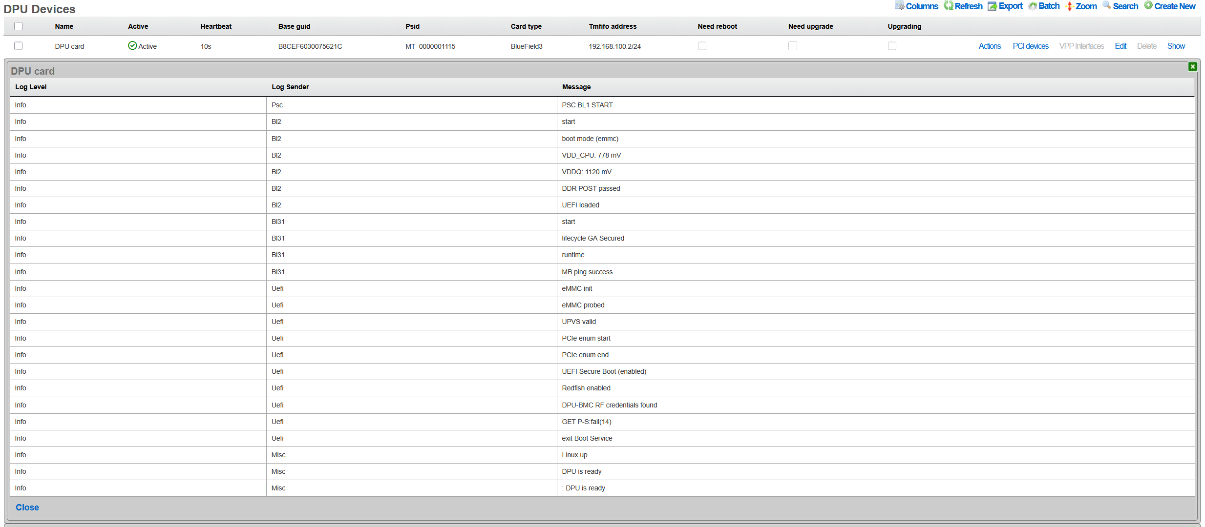
Viewing DPU Logs
Access to DPU system logs provides detailed insights into operational events and potential issues. Administrators can quickly access recent log entries by navigating to the DPU Devices section within the Network menu and selecting the Last Logs option for the target DPU. These logs contain system messages from the DPU's operating system, including kernel messages, service status changes, and error conditions. The log viewer presents entries in reverse chronological order, with the most recent events appearing first, and includes timestamp information for precise event correlation. Log entries are categorized by severity level, making it easy to identify critical issues that require immediate attention versus informational messages that provide operational context.
Health Notifications
The automated notification system ensures that administrators are promptly informed of significant health events affecting DPU operations. DPU offline events generate WARNING severity notifications when a device becomes unreachable, providing early warning of potential failures. SSH credential failures trigger FATAL severity alerts, as these prevent the rXg from managing the DPU and require immediate resolution. Firmware version mismatches between installed and running versions generate notifications to remind administrators that a reboot is required to activate updates. Temperature threshold violations produce alerts with escalating severity based on how far the temperature exceeds normal operating ranges. RSHIM communication failures generate critical notifications as they indicate a complete loss of management connectivity to the DPU. These notifications can be configured to trigger email alerts, SNMP traps, or webhook calls to integrate with existing monitoring infrastructure.
VPP Integration
Overview
Vector Packet Processing (VPP) represents a critical component of the rXg DPU architecture, providing a high-performance userspace packet processing framework that leverages the DPU's hardware acceleration capabilities. VPP operates as a software dataplane that processes packets in batches, achieving near line-rate performance while maintaining flexibility for complex network functions. The rXg platform automatically manages VPP version 25.02 or newer on DPUs, ensuring compatibility with the latest performance optimizations and feature sets.
The integration between rXg and VPP enables sophisticated packet processing pipelines that combine the flexibility of software-defined networking with the performance of hardware acceleration. VPP's graph-based architecture allows packets to flow through a series of processing nodes, each performing specific functions such as routing, filtering, encapsulation, or encryption. This modular approach enables administrators to construct complex network services without sacrificing performance.
VPP Configuration
The automated VPP configuration process begins immediately after successful DPU initialization. The system first establishes a secure connection to the DPU's operating system and verifies the current software state. It then proceeds to configure the FD.io (Fast Data Input/Output) package repositories, which provide access to the latest stable VPP releases and associated plugins. The repository configuration includes GPG key verification to ensure package authenticity and integrity.
Package installation follows a carefully orchestrated sequence that accounts for dependencies and version compatibility. The system installs the core VPP package along with essential plugins and libraries required for rXg integration. To prevent inadvertent updates that might introduce incompatibilities, the system implements APT package holds on critical VPP components, ensuring that automated system updates do not disrupt the carefully tuned VPP configuration.
One of the most important components deployed during VPP configuration is the L2 Open GRE (l2ogre) plugin, which enables high-performance Layer 2 tunneling over GRE (Generic Routing Encapsulation). This plugin provides essential functionality for extending Layer 2 networks across Layer 3 infrastructure, supporting use cases such as distributed switching, VXLAN gateway services, and seamless VM migration across data centers. The l2ogre plugin integrates directly with VPP's graph processing architecture, ensuring minimal latency and maximum throughput for tunneled traffic.
Physical interface mapping represents the final critical step in VPP configuration. The system automatically identifies all network interfaces connected to the DPU and determines which should be managed by VPP versus those reserved for system management. Data plane interfaces are detached from the kernel networking stack and attached to VPP, where they benefit from poll-mode drivers and zero-copy packet processing. The mapping process preserves interface naming consistency and maintains correlation between physical ports and their VPP representations.
Interface Management
The rXg interface management system provides a unified view of DPU network resources, abstracting the complexity of VPP-managed interfaces while maintaining full visibility and control. Physical interfaces represent the actual hardware ports on the DPU, typically showing as mlx5_core devices in the system. These interfaces connect directly to network infrastructure and handle the physical transmission and reception of packets.
Pseudo interfaces serve as the VPP-managed virtual representations of physical interfaces, providing the abstraction layer necessary for software-defined networking operations. These interfaces exist entirely within the VPP dataplane and can be configured with advanced features such as bonding, sub-interfaces for VLAN tagging, and tunnel endpoints. The pseudo interface abstraction allows administrators to configure complex networking topologies without directly manipulating the underlying hardware.
Interface Type 5 designation within the rXg system specifically identifies DPU VPP interfaces, distinguishing them from traditional kernel-managed network interfaces. This classification enables the rXg policy engine to apply appropriate configuration templates and management procedures specific to VPP-accelerated interfaces. The Type 5 designation also triggers specialized monitoring and statistics collection suited to VPP's high-performance characteristics.
The interface lifecycle management includes automatic recovery mechanisms for various failure scenarios. If a VPP crash occurs, the system automatically detects the failure through heartbeat monitoring and initiates recovery procedures. These procedures include restarting the VPP service, reapplying interface configurations, and restoring traffic flows. The recovery process typically completes within seconds, minimizing service disruption.
Viewing VPP Status
Monitoring VPP operations requires understanding both the high-level service status and detailed performance metrics. The rXg interface provides comprehensive visibility into VPP operations through multiple viewing contexts. By navigating to Network DPU DPU Devices and selecting a specific DPU, administrators gain access to real-time status information and historical data.
The VPP Interfaces link presents a detailed view of all VPP-managed interfaces, including their operational status, configuration parameters, and performance statistics. Each interface entry shows packet and byte counters, error statistics, and queue utilization metrics. The interface mapping table correlates physical ports with their VPP representations, making it easy to trace traffic flows through the system. Advanced statistics include detailed histograms of packet sizes, inter-packet arrival times, and processing latencies.
Performance metrics are collected continuously and stored in a time-series database for historical analysis. Administrators can view throughput graphs, latency measurements, and resource utilization trends over various time periods. This historical data proves invaluable for capacity planning, performance optimization, and troubleshooting intermittent issues.
VPP Logs
The VPP logging system provides detailed insights into service operations, configuration changes, and error conditions. When VPP requires restart due to configuration changes or error recovery, the system maintains comprehensive logs of the event sequence. Accessing these logs through Network DPU DPU Devices VPP Restart Logs reveals the complete restart history, including timestamps, triggering conditions, and recovery actions. Additionally, the Last Logs action provides access to the DPU's system log messages for general troubleshooting.
Log entries include multiple severity levels ranging from debug messages that detail packet processing decisions to critical errors that indicate service failures. The logging system implements intelligent filtering to prevent log flooding while ensuring that important events are captured. Each log entry includes contextual information such as the affected interface, processing graph node, and relevant packet headers when applicable.
The log analysis tools within rXg can correlate VPP logs with system events, providing a comprehensive view of DPU operations. This correlation helps identify patterns such as configuration changes that trigger VPP restarts or network conditions that cause packet processing errors. Administrators can configure alerts based on specific log patterns, enabling proactive monitoring and rapid response to potential issues.
L2oGRE (SoftGRE) Integration
The rXg DPU architecture provides hardware-accelerated Layer 2 GRE tunneling through the l2ogre VPP plugin. This integration enables high-performance bridging of Layer 2 traffic across Layer 3 networks, commonly used for wireless access point deployments where client traffic is tunneled back to the rXg for policy enforcement, authentication, and internet access.
Underlay vs Overlay Network Architecture
Understanding the distinction between underlay and overlay networks is essential for proper L2oGRE configuration:
Underlay Network: The physical or logical network that carries the GRE-encapsulated packets. This is typically the VLAN where access points and the rXg communicate. For example, VLAN 100 might serve as the underlay, providing IP connectivity between APs and the rXg. The underlay VLAN carries the outer IP headers of the GRE tunnel.
Overlay Networks: The VLANs being transported inside the GRE tunnels. These represent the actual client networks (e.g., guest VLAN 200, corporate VLAN 300). From the perspective of clients and the overlay VLANs, traffic appears to be locally bridgedthey are unaware that their packets are being encapsulated and transported over the underlay network.
VLAN Selection for L2oGRE Bridging
The system automatically determines which VLANs participate in L2oGRE bridging based on explicit configuration and network address overlap analysis:
Direct Association: VLANs explicitly assigned to the L2oGRE pseudo interface through the rXg configuration interface are automatically included in L2oGRE bridging. These VLANs must belong to the local cluster node to be configured.
Whitelist-Based Selection: For DPU/VPP L2oGRE bridging, the system performs intelligent VLAN selection based on:
WAN Targets: If WAN targets are associated with the L2oGRE pseudo interface, VLANs whose configured IP addresses overlap with those WAN target networks are whitelisted for L2oGRE bridging.
Policies with IP Groups: If policies are associated with the L2oGRE pseudo interface, VLANs whose addresses overlap with the IP groups defined in those policies are whitelisted.
Address Overlap Analysis: The system evaluates each VLAN's configured addresses against the WAN targets and IP groups. A VLAN is whitelisted if any of its addresses fall within (or contain) the defined network ranges.
This automated selection ensures that only relevant VLANs participate in L2oGRE bridging, optimizing resource utilization and preventing unintended traffic flows.
NAT and L2oGRE Considerations
A critical architectural consideration when deploying L2oGRE on DPUs involves Network Address Translation (NAT) processing. This applies to all NAT variants supported by VPP, including NAT44, NAT46, NAT64, and NAT66.
VPP Limitation: VPP interfaces configured to receive SoftGRE packets cannot simultaneously perform NAT processing. This is a fundamental limitation of the VPP packet processing pipelinean interface must choose between being a GRE tunnel endpoint or a NAT translation point.
Underlay VLAN Behavior: The underlay VLAN (the network carrying GRE-encapsulated traffic) has NAT automatically disabled in VPP when L2oGRE is enabled. This is typically not a concern because:
- The underlay VLAN's primary purpose is to transport tunneled traffic between APs and the rXg
- Devices on the underlay network (primarily APs) that require internet access use the rXg as their default gateway
- Traffic from underlay devices is processed by the rXg's standard routing and NAT infrastructure, bypassing VPP NAT
Overlay VLAN Behavior: Overlay VLANs (the client networks transported inside GRE tunnels) function normally with full NAT support. From the perspective of these VLANs, traffic appears to be locally bridgedthey are unaware of the GRE encapsulation. NAT processing occurs as packets egress through the appropriate WAN interface, completely independent of the L2oGRE tunnel processing.
Example Deployment Scenario
Consider a typical deployment with the following configuration:
VLAN 100 (Underlay): Management/AP network, 10.100.0.0/24
- Access points connect here
- rXg address: 10.100.0.1 (default gateway for APs)
- NAT disabled in VPP (by design)
- APs needing internet access route through rXg normally
VLAN 200 (Overlay): Guest wireless, 10.200.0.0/24
- Client traffic tunneled from APs via GRE
- Full NAT support in VPP
- Clients see the rXg as their default gateway
VLAN 300 (Overlay): Corporate wireless, 10.300.0.0/24
- Client traffic tunneled from APs via GRE
- Full NAT support in VPP
- May have different policies than guest network
In this scenario, guest and corporate clients on VLANs 200 and 300 experience full DPU-accelerated NAT and policy enforcement. The underlay VLAN 100 provides reliable transport for the tunneled traffic, with AP management traffic handled through traditional rXg routing.
Configuring L2oGRE for DPU
To enable L2oGRE on DPU:
- Navigate to Network Pseudo Interfaces
- Create or edit an L2oGRE pseudo interface
- Set the SoftGRE Operation Mode to one of the following:
- Enable All Modes: L2oGRE processing on both DPU/VPP and the traditional host daemon
- Host Mode: L2oGRE processing handled by the traditional host daemon only
- DPU: L2oGRE processing handled exclusively by DPU/VPP hardware acceleration
- Associate the appropriate VLANs with the pseudo interface (these are the underlay VLANs that will transport tunneled traffic)
- Configure WAN targets and/or policies to whitelist overlay VLANs (at least one is required for L2oGRE to function)
- Configure GRE key mode and other tunnel parameters as needed
The system automatically generates the VPP configuration, creates the necessary bridge domains, and establishes the L2oGRE tunnel interfaces.
Troubleshooting
Common Issues and Solutions
DPU Not Detected
Symptoms: No DPU appears in device list
Solutions:
1. Verify physical installation:
bash
   pciconf -lv | grep -i mellanox
2. Check kernel module:
bash
   kldstat | grep cuse
3. Restart RSHIM service:
bash
   service rshim restart
Firmware Upgrade Stuck
Symptoms: Upgrade status remains "upgrading" > 1 hour
Solutions:
1. Check RSHIM device:
bash
   ls -la /dev/rshim*/boot
2. View upgrade logs via Upgrade History
3. Perform software reset:
- Click Software Reset on DPU device
4. If unresponsive, power cycle host system
VPP Not Running
Symptoms: No pseudo interfaces visible
Solutions:
1. Check VPP service on DPU:
bash
   ssh [email protected] "sudo systemctl status vpp"
2. Review VPP logs:
bash
   ssh [email protected] "sudo journalctl -u vpp -n 50"
3. Restart VPP:
bash
   ssh [email protected] "sudo systemctl restart vpp"
Network Performance Issues
Symptoms: Lower than expected throughput
Solutions:
1. Verify PCIe link speed:
bash
   pciconf -lc pci0:42:0:0 | grep "Link Speed"
2. Check DPU temperature:
- High temperatures throttle performance
3. Review interface statistics for errors
4. Ensure TSO/LRO offloads are configured correctly
Advanced Diagnostics
Accessing DPU Console
For direct DPU access: ```bash
Via TMFIFO SSH
ssh [email protected] ```
Checking RSHIM Status
To verify RSHIM communication: ```bash
Read RSHIM misc information
cat /dev/rshim0/misc
View JSON telemetry
cat /dev/rshim0/misc_json | python -m json.tool ```
API Reference
REST API Endpoints
The rXg provides REST API access for DPU management through standard RESTful endpoints:
DPU Devices (/api/dpu_devices):
- GET /api/dpu_devices - List all DPU devices
- GET /api/dpu_devices/{id} - Get specific DPU details
- POST /api/dpu_devices - Create a new DPU device record
- PUT /api/dpu_devices/{id} - Update DPU configuration
- DELETE /api/dpu_devices/{id} - Delete a DPU device record
DPU Software (/api/dpu_device_softwares):
- GET /api/dpu_device_softwares - List available firmware packages
- GET /api/dpu_device_softwares/{id} - Get specific firmware details
- POST /api/dpu_device_softwares - Upload new BFB file
- DELETE /api/dpu_device_softwares/{id} - Delete a firmware package
Note: Administrative actions such as software reset and firmware upgrade are performed through the web UI scaffold interface rather than the REST API.
Authentication
API requests require authentication via:
- API key in header: X-API-Key: [key]
- OAuth 2.0 bearer token
- Session cookie (web UI)
Example API Usage
# List DPU devices
curl -H "X-API-Key: your-api-key" \
  https://rxg.example.com/api/dpu_devices

# Get specific DPU device details
curl -H "X-API-Key: your-api-key" \
  https://rxg.example.com/api/dpu_devices/1

# Update DPU device configuration
curl -X PUT -H "X-API-Key: your-api-key" \
  -H "Content-Type: application/json" \
  -d '{"name": "Production DPU 1", "tmfifo_address": "192.168.100.2"}' \
  https://rxg.example.com/api/dpu_devices/1

# Upload BFB firmware
curl -X POST -H "X-API-Key: your-api-key" \
  -F "filename=bf-bundle-3.1.0-76_25.07_ubuntu-22.04_prod.bfb" \
  -F "bfb_file=@/path/to/firmware.bfb" \
  https://rxg.example.com/api/dpu_device_softwares


