VPN
The VPN view presents the scaffolds associated with configuring the IPsec, OpenVPN, and WireGuard services integrated into the rXg. A quick comparison of individual supported VPN solutions is shown below:
| Feature | WireGuard | OpenVPN | IPsec |
|---|---|---|---|
| Performance | Very fast (kernel-level, minimal code) | Moderate (user-space, slower) | High (varies by implementation) |
| Ease of Setup | Simple (few lines of config) | More complex (certs, configs) | Complex (many options, key exchanges) |
| Security | Modern cryptography (ChaCha20, etc.) | Strong, but older ciphers | Strong, supports many ciphers |
| Codebase Size | ~4,000 lines (easily auditable) | >100,000 lines (harder to audit) | Very large (varies widely) |
| Cross-Platform | Yes (Linux, Windows, macOS, mobile) | Yes | Yes |
| NAT Traversal | Built-in | Built-in | Sometimes requires extra config/tools |
OpenVPN Servers
Entries in the OpenVPN Servers scaffold define configuration profiles for the rXg integrated SSL(TLS) VPN.
OpenVPN is an industry standard, open-source software application that the rXg leverages to implement virtual private network (VPN) techniques to create secure point-to-point connections in a routed configuration. It uses a custom security protocol that utilizes SSL/TLS for key exchange. It is capable of traversing network address translators (NATs) and firewalls. The OpenVPN functionality allows peers to authenticate each other using certificates and/or username/password. When used in a multiclient-server configuration, it allows the server to release an authentication certificate for every client, using signatures and certificate authority. It uses the OpenSSL encryption library extensively, as well as the TLS protocol, and contains many security and control features.
https://community.openvpn.net/openvpn/wiki
The name field is an arbitrary string descriptor used only for administrative identification. Choose a name that reflects the purpose of the record. This field has no bearing on the configuration or settings determined by this scaffold.
Each server represents a virtual network interface on a subnet specified by a related Network Address. A separate VPN instance exists for each configured server. A Network Address that is assigned to an OpenVPN interface cannot be configured on a traditional ethernet Interface or VLAN. All servers/networks operate in OpenVPN's TUN (tunnel) mode, which transports only layer 3 IP packets.
If the default gateway field is checked the client will use the VPN interface's IP as its default gateway and DNS server, and route everything over the VPN. An OpenVPN server's Network Address behaves similarly to any other routed subnet behind an ethernet interface or VLAN, in that IP clients behind it are subject to Policy enforcement. For example, creating an IP Group and Landing Portal Policy without a subnet filter for the VPN network would permit the client to access all networks. Conversley, a portal-enabled Policy could be deployed for the VPN client's network. If gateway redirect is not enabled on the server, then it will push routes for all other local networks to a VPN client, which allows it to route through the normal Internet whilst also having knowledge of networks behind the VPN. Note that like any other traditionally-attached subnet, or when the VPN is the default gateway, the routes pushed to the client do not necessarilly ensure firewall access to all networks. In general, an OpenVPN client can also manipulate its routing table independently on a per-client basis.
Authentication from a client may be multi or single-factor via certificates ( require certificate ) and/or username/password ( require login ). If certificates are required, clients must have a unique certificate installed to authenticate. The certificate must be signed by the same CA as the OpenVPN Server's certificate. If multiple devices need to use the same client certificate, the allow duplicate certificates field must be checked, otherwise only one connection per certificate Common Name is permitted. Requiring a unique certificate per client is more secure, but requires each client to have a unique configuration.
If client-to-client behavior is enabled, then clients on the same virtual network can route to each other as if the firewall was disabled. This does not include L2 traffic. Otherwise, if this behavior is disabled, all traffic is forced to route through the rXg and is thus filtered according to Policy enforcement. This should only be enabled when_everyone_ connecting to the same OpenVPN Server should be allowed to communicate.
Configuring the Admin Roles field restricts VPN access to administrators with specific roles. This is useful for providing remote management access, implementing role-based network access, and segregating administrative domains.
Configuring the Account Groups field allows end-users in selected groups to connect to the VPN. This enables premium VPN services for specific customer tiers, employee remote access by department, and guest VPN access with limited permissions. If client certificates are required, the login is only half the authentication process. If client login is not required then these selections are ignored.
It is recommended that operators (Admins) and end-users (Accounts) connect to separate OpenVPN Servers. In the case where an OpenVPN Server has both Admins and Accounts allowed, an Admin having the same login as an Account always takes precedence for login and instrumentation purposes.
The port and protocol fields define how a client initially connects to the VPN server. A TCP and UDP server may be configured to run on the same port. There are advantages and disadvantages to either protocol (OpenVPN tcp vs udp).
An OpenVPN Server must have a Certificate configured. This identifies the server's certificate and private key in additon to the Certificate Authority (CA) that establishes the PKI used to trust clients. The selected Certificate must be associated with and created from a local Certificate Authority. The certificate must be marked for server usage, meaning it was signed with an explicit key usage and extended key usage based on RFC3280 TLS rules. This can be done when creating the Certificate Signing Request (CSR). This is an important security precaution to protect against a man-in-the-middle attack where an authorized client attempts to connect to another client by impersonating the server.
The cipher algorithm encrypts the data channel. Available options include: - AES-256-GCM: Highest security, AEAD cipher (recommended for new deployments) - AES-192-GCM: Balance of security and performance - AES-128-GCM: Good performance, adequate security for most uses - AES-256-CBC: Legacy mode, highest security for older clients - AES-192-CBC: Legacy mode, balance of security and performance - AES-128-CBC: Legacy mode for compatibility with older clients
The digest (authentication) algorithm provides HMAC authentication: - SHA512: Highest security, more CPU intensive - SHA256: Recommended balance of security and performance (default) - SHA1: Legacy support only, should be avoided for new deployments
Note: GCM ciphers include built-in authentication, making them more secure and efficient.
Data compression options include: - lz4-v2: Newest and most efficient LZ4 implementation with improved framing - lz4: Fast compression with low CPU overhead (recommended) - lzo: Legacy compression, compatible with older clients - off: Disable compression (recommended for already-compressed traffic like HTTPS)
Compression reduces bandwidth usage for uncompressed traffic but adds CPU overhead. It may actually increase bandwidth for already-compressed data and should be disabled for primarily HTTPS traffic.
The TLS Auth option adds an additional layer of HMAC authentication on top of TLS to mitigate DoS and other attacks against the TLS layer. This is accomplished by including a unique key that resides on top of TLS. The key is generated behind the scenes when an OpenVPN Server is created, and included in the client config output. If a client is configured manually and this is enabled, then the operator must obtain the key from the record via scaffold show action.
The keepalive ping and keepalive ping restart parameters control connection monitoring. The keepalive ping interval (default: 10 seconds) determines how frequently keepalive pings are sent to maintain connections through stateful firewalls. The keepalive ping restart timeout (default: 120 seconds) determines how long to wait before considering a connection dead and restarting it. These settings help maintain connections through stateful firewalls and detect failed connections quickly.
The MSS fix parameter (Maximum Segment Size) helps prevent fragmentation at the TCP layer by limiting the size of TCP data packets. The valid range is 1200-1460 bytes, with the default of 1432 working well for most deployments. This may need adjustment based on the underlying network MTU, overhead from additional encapsulation (PPPoE, etc.), and performance requirements.
The fragment option enables OpenVPN to fragment packets at the application layer to work around path MTU discovery issues. This is particularly useful when the VPN must traverse networks that have MTU restrictions. For UDP connections, if fragmentation is enabled, MSS fix inherits the fragment maximum value.
The debug mode option enables verbose logging for troubleshooting connection issues. When enabled, detailed connection logs are written to /var/log/openvpn.log. This should only be enabled for troubleshooting as it increases log volume significantly.
WAN Targets provide access control for OpenVPN servers accessible from the WAN. To enable WAN access, specify one or more WAN targets containing the list of allowed source IP addresses or networks. If no WAN target is specified and WAN visibility is enabled, any node on the WAN may connect to the service. It is highly recommended that this wide-open configuration be avoided to ensure system security. WAN targets support both individual IP addresses and CIDR network ranges.
The note field is a place for the administrator to enter a comment. This field is purely informational and has no bearing on the configuration settings.
Clicking the Download Config link will generate an OpenVPN config (.ovpn) file containing the necessary client connection parameters based on the server's configuration, including the Server certificate. Currently, if a client certificate is required, it must be generated manually via the local CA and installed in the client along with the config file.
Advanced OpenVPN Server Features
Fragmentation and MSS Settings
The fragment option enables OpenVPN to fragment packets at the application layer to work around path MTU discovery issues. This is particularly useful when the VPN must traverse networks that have MTU restrictions.
The mssfix parameter (Maximum Segment Size) helps prevent fragmentation at the TCP layer by limiting the size of TCP data packets. The valid range is 1200-1460 bytes. The default value of 1432 works well for most deployments, but may need adjustment based on: - Underlying network MTU - Overhead from additional encapsulation (PPPoE, etc.) - Performance requirements
For UDP connections: - If fragmentation is enabled, mssfix inherits the fragment maximum value - If fragmentation is disabled, mssfix operates independently - TCP connections do not use mssfix as TCP has built-in MSS negotiation
Keepalive Settings
The keepalive ping and keepalive ping restart parameters control connection monitoring:
- keepalive ping: Interval in seconds between keepalive pings (default: 10)
- keepalive ping restart: Timeout in seconds before considering the connection dead and restarting (default: 120)
These settings help maintain connections through stateful firewalls and detect failed connections quickly. Adjust based on: - Network reliability - Firewall timeout settings - Desired failover speed - Battery considerations for mobile clients
Compression Options
OpenVPN supports multiple compression algorithms:
- lz4-v2: Newest and most efficient LZ4 implementation with improved framing
- lz4: Fast compression with low CPU overhead (recommended)
- lzo: Legacy compression, compatible with older clients
- off: Disable compression (recommended for already-compressed traffic like HTTPS)
Compression considerations: - Reduces bandwidth usage for uncompressed traffic - Adds CPU overhead on both client and server - May actually increase bandwidth for already-compressed data - Can potentially be exploited in CRIME/BREACH-style attacks on HTTPS traffic
Certificate Management
Advanced certificate options include:
Allow duplicate certificates: When enabled, multiple clients can connect using the same certificate. This is less secure but simplifies deployment when: - Multiple devices need to share credentials - Temporary access needs to be granted quickly - Legacy systems cannot support unique certificates
Require certificate: Controls whether clients must present a valid certificate: - When enabled with require login: Two-factor authentication (certificate + password) - When enabled without require login: Certificate-only authentication - When disabled: Username/password authentication only
The certificate chain is validated against the Certificate Authority specified in the SSL Key Chain. Ensure: - Certificates are marked for appropriate usage (server vs client) - Certificate dates are valid - The CA chain is complete and trusted - Revoked certificates are properly managed
Cipher and Authentication Algorithms
The cipher algorithm encrypts the data channel: - AES-256-GCM: Highest security, AEAD cipher (recommended for new deployments) - AES-192-GCM: Balance of security and performance - AES-128-GCM: Good performance, adequate security for most uses - AES-xxx-CBC: Legacy mode for compatibility with older clients
The authentication algorithm provides HMAC authentication: - SHA512: Highest security, more CPU intensive - SHA256: Recommended balance of security and performance - SHA1: Legacy support only, should be avoided for new deployments
Note: GCM ciphers include authentication, making the separate auth setting less relevant.
TLS Authentication
The TLS Auth feature adds an additional HMAC signature to all TLS handshake packets, providing: - Protection against DoS attacks on the TLS stack - Prevention of port scanning detection - Additional authentication layer before TLS negotiation
The TLS auth key is automatically generated when the server is created and included in client configurations. For manual client configuration, the key can be obtained from the scaffold show action.
Access Control Integration
OpenVPN Servers integrate with the rXg's access control system:
Admin Roles: Selecting specific admin roles restricts VPN access to administrators with those roles. This is useful for: - Providing remote management access - Implementing role-based network access - Segregating administrative domains
Account Groups: Selecting account groups allows end-users in those groups to connect. This enables: - Premium VPN services for specific customer tiers - Employee remote access by department - Guest VPN access with limited permissions
When both are configured, administrators take precedence over regular accounts with the same username.
Performance Tuning
For optimal OpenVPN performance:
Protocol Selection:
- UDP: Lower latency, better for real-time applications
- TCP: Better for restrictive firewalls, may cause TCP meltdown
Cipher Selection:
- Use GCM ciphers when possible (hardware acceleration on modern CPUs)
- Avoid CBC ciphers unless required for compatibility
Compression:
- Disable for primarily HTTPS traffic
- Enable LZ4 for mixed traffic types
- Monitor CPU usage when enabled
Buffer Sizes:
- Adjust mssfix based on measured path MTU
- Enable fragment only when necessary
Concurrent Connections:
- Each OpenVPN server process is single-threaded
- For high connection counts, run multiple servers on different ports
- Use UDP for better scaling
OpenVPN Client Configuration
Once the server is configured and the .ovpn configuration file is downloaded, it can be imported into OpenVPN clients on various platforms. The following examples show how to configure popular OpenVPN clients:
Android (OpenVPN Connect)
- Install the official OpenVPN Connect app from Google Play Store
- Open the app and tap the + icon to add a profile
- Select Import Profile File
- Navigate to and select the downloaded .ovpn file
- The profile will be imported automatically with all settings from the server
- If username/password authentication is required, enter credentials when prompted
- Tap the profile name to connect to the VPN
- Grant VPN permission when Android requests it
The connection status will show in the app and Android's notification bar. To disconnect, tap the profile again or use the disconnect button in notifications.
iOS (OpenVPN Connect)
- Install the official OpenVPN Connect app from the App Store
- Transfer the .ovpn file to your iOS device via email, AirDrop, or cloud storage
- Open the .ovpn file, which should automatically launch OpenVPN Connect
- Tap Add to import the profile
- If username/password authentication is required, enter credentials
- Tap the toggle switch next to the profile to connect
- Grant VPN permission when iOS requests it
- The VPN icon will appear in the status bar when connected
To disconnect, return to the app and toggle the connection off, or use iOS Settings VPN.
Windows (OpenVPN GUI)
- Download and install OpenVPN GUI from the official OpenVPN website
- Copy the .ovpn configuration file to the OpenVPN config directory:
- Default location:
C:\Program Files\OpenVPN\config\ - Or:
C:\Users\[username]\OpenVPN\config\
- Default location:
- Right-click the OpenVPN GUI system tray icon
- Select Connect from the context menu for your profile
- If username/password authentication is required, enter credentials in the popup window
- The system tray icon will turn green when connected
- A notification will confirm the successful connection
To disconnect, right-click the system tray icon and select Disconnect.
macOS (Tunnelblick)
- Download and install Tunnelblick (free, open-source OpenVPN client)
- Launch Tunnelblick - it will appear in the menu bar
- Click the Tunnelblick icon and select VPN Details
- Drag and drop the .ovpn file onto the Configurations tab, or click + and browse to the file
- Enter an admin password if prompted to install the configuration
- Click Connect next to the profile name
- If username/password authentication is required, enter credentials
- The menu bar icon will change to indicate connection status
To disconnect, click the Tunnelblick menu bar icon and select Disconnect.
Linux (Network Manager / Command Line)
Using Network Manager (Ubuntu/GNOME):
1. Install the Network Manager OpenVPN plugin:
bash
   sudo apt install network-manager-openvpn network-manager-openvpn-gnome
2. Go to Settings Network VPN
3. Click the + to add a VPN connection
4. Select Import from file and choose your .ovpn file
5. Review the imported settings and add username/password if required
6. Click Add to save the configuration
7. Toggle the VPN connection on to connect
Using command line:
1. Install OpenVPN: sudo apt install openvpn
2. Copy the .ovpn file to a secure location
3. Connect using: sudo openvpn --config /path/to/your/config.ovpn
4. Enter username/password if prompted
5. Press Ctrl+C to disconnect
Windows 10/11 (Built-in VPN)
For simple configurations without certificates, Windows' built-in VPN client can be used: 1. Go to Settings Network & Internet VPN 2. Click Add a VPN connection 3. Select Windows (built-in) as the VPN provider 4. Enter connection details: - Connection name: Descriptive name - Server name or address: rXg's public IP or domain - VPN type: Select appropriate protocol - Sign-in info: Username and password 5. Click Save 6. Click the connection name to connect
Note: This method works best with simple username/password authentication. For certificate-based authentication, use OpenVPN GUI instead.
Troubleshooting Client Connections
Connection Fails: - Verify the server address is correct and accessible - Check that firewall rules allow the OpenVPN port (default 1194) - Ensure the client device has internet connectivity - Try connecting from a different network to rule out local firewall issues
Authentication Errors: - Double-check username and password if using credential authentication - Verify certificates are properly embedded in the .ovpn file - Check that the client certificate hasn't expired - Ensure the CA certificate matches the server's certificate authority
Connected but No Internet: - Check if "redirect gateway" is enabled on the server (routes all traffic through VPN) - Verify DNS settings - try using public DNS servers (8.8.8.8, 1.1.1.1) - Test connectivity to the rXg's LAN network first - Check MTU settings if web browsing is slow or fails
Performance Issues: - Try UDP protocol instead of TCP if experiencing slowdowns - Disable compression if connecting over already-compressed connections - Check for MTU/MSS issues with large file transfers - Monitor CPU usage on both client and server during heavy usage
Mobile Device Battery Drain: - Adjust keepalive settings on the server to reduce ping frequency - Use on-demand VPN connections when possible - Consider split-tunneling to reduce VPN traffic for non-sensitive apps
OpenVPN Operational Management
Logging and Debugging
OpenVPN logs are written to multiple locations:
- System log: Basic connection/disconnection events via syslog
- OpenVPN log: Detailed logs at
/var/log/openvpn.log - Debug mode: When enabled on server or client, increases verbosity
Log levels can be controlled through the configuration: - Level 0: No output except fatal errors - Level 3: Normal usage (default) - Level 5: Useful for debugging - Level 9: Extremely verbose
Process Management
OpenVPN servers run as separate daemon processes. Management commands:
- Restart without disconnecting clients: Send SIGUSR1 to the process
- Full restart with configuration reload: Send SIGHUP to the process
- Graceful shutdown: Send SIGTERM to the process
The process name format is openvpn_server_[port]_[protocol] for servers and openvpn_client_[name] for clients.
Monitoring and Health Checks
Monitor OpenVPN health through:
Connection Status:
- Check OpenVPN Entries for active sessions
- Monitor the online status of OpenVPN Clients
- Review connection logs for authentication failures
Performance Metrics:
- CPU usage per OpenVPN process
- Bandwidth utilization per tunnel
- Packet loss and latency through tunnels
Certificate Expiration:
- Monitor server certificate expiration dates
- Track client certificate validity
- Plan CA certificate renewal
Common Issues and Solutions
Connection Failures: - Verify firewall rules permit the OpenVPN port - Check certificate validity and trust chain - Ensure time synchronization (certificates are time-sensitive) - Verify network connectivity to the remote endpoint
Performance Issues: - Disable compression for encrypted traffic - Adjust mssfix for optimal packet size - Use UDP instead of TCP when possible - Check CPU usage and consider cipher changes
Routing Problems: - Verify no IP range conflicts between sites - Check that routes are properly pushed to clients - Ensure IP forwarding is enabled - Validate NAT rules for client traffic
Authentication Failures: - Check username/password credentials - Verify certificate signatures and CA chain - Ensure certificates are marked for correct usage - Check for account lockouts or disabled users
Security Best Practices
Use Strong Encryption:
- Deploy AES-256-GCM for new installations
- Enable TLS Auth for DoS protection
- Use SHA256 or higher for authentication
Certificate Management:
- Use unique certificates per client when possible
- Implement certificate revocation lists (CRL)
- Set appropriate certificate lifetimes
- Protect private keys appropriately
Access Control:
- Implement least-privilege access policies
- Use two-factor authentication for sensitive access
- Regularly audit VPN access logs
- Disable unused VPN servers
Network Segmentation:
- Place VPN clients in dedicated subnets
- Apply appropriate firewall policies
- Disable client-to-client routing unless required
- Monitor for unusual traffic patterns
IPsec VPN
IPsec is an industry standard mechanism that enables secure communication between two nodes or networks that are connected by a potentially insecure IP transit. The rXg supports bidirectional site-to-site IPsec VPNs between rXgs and between rXgs and other kinds of routers. In addition, the rXg may be configured to be a concatenator for host-to-site VPNs originating from nearly any operating system.

Site-to-site VPNs are typically used to enable secure bidirectional communication between two private IP blocks that are behind different routers that are located in geospatially distinct locations. For example, if a WISP has three distinct fixed wireless broadband coverage areas, all three could be linked together via site-to-site VPNs. This could be used as part of a revenue generation strategy such as allowing business customers to access their systems from home for an additional fee.

Site-to-site VPNs are very useful in geospatially diverse deployments that are connected via a central cluster controller. Establishing site-to-site VPNs between the rXgs and the cluster controller enables the operator to easily access all nodes at any part of the network. It is important to keep in mind that the private LAN addresses blocks behind the various rXgs be kept distinct as having the same private LAN block behind two rXgs would cause routing confusion.

Host-to-site VPNs are often used by operators for remote administration. An operator that is on the WAN side of a rXg may use host-to-site IPsec VPNs to directly access machines that are connected to a private address range. In a typical deployment, LAN equipment is assigned IP addresses from private ranges that cannot be reached from the WAN. An operator who is on the WAN side on the rXg (e.g., away on business) that wishes to have complete and direct access to the LAN equipment private address range would setup a host-to-site IPsec VPN using the rXg as the concatenator.

Host-to-site VPNs are also used as a revenue generation mechanism as they are typically sold as a premium service or as a value-added extra part of business class service. End-users originating traffic from the LAN side of the rXg may create a host-to-site VPN using the rXg as a concatenator to protect their traffic from sniffers present in the distribution network. Of course, end-users may also be sold host-to-site VPNs as a mechanism for remote connectivity to nodes addressed on a private LAN.
The rXg uses an industry standard reference implementation of the IPsec suite. Site-to-site VPNs are easily established between an rXg and nearly any other router that supports IPsec VPNs. In addition, site-to-site and site-to-host VPNs may be established between the rXg and almost any operating system released since 2005. Most operating systems have a built-in IPsec stack that is meant to be configured by a trained and certified specialist. However, VPN client software (e.g., Greenbow for Windows and IPsecuritas for Mac OS X) simplify the process to the extent that anybody with a working knowledge of basic TCP/IP can accomplish the task.
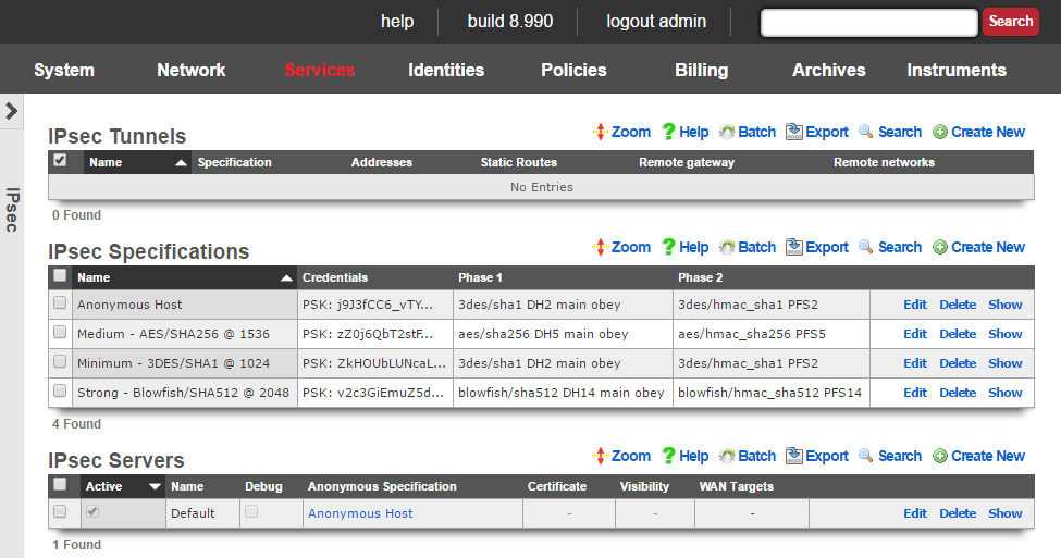
IPsec Tunnels
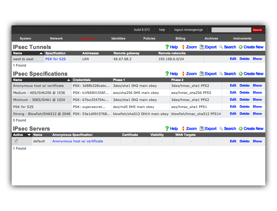
An entry in the IPsec tunnels scaffold is used to configure a site-to-site IPsec VPN.
The name field is an arbitrary string descriptor used only for administrative identification. Choose a name that reflects the purpose of the record. This field has no bearing on the configuration or settings determined by this scaffold.
The specification field selects the credential and encryption settings for this IPsec tunnel. It is critically important to ensure that the settings in the chosen IPsec specification matches those of the node at the other end of the site-to-site VPN created by this IPsec tunnel.
The Pre-Shared key and Certificates fields are used to configure the certificates or pre-shared key that will be used for authenticating IPsec tunnels that use this IPsec specification. The operator may choose to use one or more certificates or a pre-shared key but not both. If one or more certificates are chosen, then the node at the other end of the IPsec tunnel must have the matching private key. If a pre-shared key is chosen, then the node at the other end of the IPsec tunnel must have the exact same pre-shared key programmed.
The addresses and static routes checkboxes specify which LAN address blocks will be forwarded to the remote node of this site-to-site VPN.
The remote gateway field specifies the IP address of the node at the other end of this site-to-site IPsec VPN.
The remote networks field specifies the IP address blocks at the other end of this site-to-site VPN that will be routable once the VPN is established.
Conflicts between addresses or static routes and remote networks will cause severe routing problems. In situations where multiple site-to-site VPNs will be deployed, it is critically important to carefully plan the addressing across all current and potential future networks.
The note field is a place for the administrator to enter a comment. This field is purely informational and has no bearing on the configuration settings.
IPsec Specifications
An entry in the IPsec specifications scaffold defines an IPsec policy that can be used for bidirectional site-to-site VPN tunnels as well as host-to-site VPN concatenation.
The name field is an arbitrary string descriptor used only for administrative identification. Choose a name that reflects the purpose of the record. This field has no bearing on the configuration or settings determined by this scaffold.
The note field is a place for the administrator to enter a comment. This field is purely informational and has no bearing on the configuration settings.
The IKE Version field allows the operator to select which IKE(Internet Key Exhange) version to use for the tunnel. IKEv1 and IKEv2 are supported.
The phase 1 and phase 2 groups are used to configure the encryption specifications for the initialization and operational phases of a IPsec tunnel. The chosen encryption , authentication , Diffie-Hellman group , exchange mode and proposal check must exactly match the settings on the node at the other end of the IPsec tunnel.
The encryption field specifies the algorithm that will be used for bulk encryption of the packet data that will transit the VPN connection. The DES option is included for reference only and should be avoided as it is trivially broken given contemporary computing power. The 3DES and AES options are the most compatible and generally accepted to be strong enough for most purposes. AES is preferable as it is the new government standard encryption protocol. Blowfish and CAST are less known protocols but widely believed to be as strong if not stronger than AES but not as well supported.
The authentication field specifies the algorithm that will be used for generating cryptographic hashes to authenticate data passing through the VPN connection. The MD5 option is included for reference only and should be avoided as researchers have discovered methods to break it. The SHA1 option is the most compatible option as it is broadly supported. If possible, the SHA256, SHA384 or SHA512 options as researchers have found a handful of minor vulnerabilities in SHA1 to date.
The Diffie-Hellman group and PFS group fields configure the strength of the encryption keys that will be used to protect the session keys used by the encryption algorithm. The stronger the key, the less likely that it will be broken. However, the stronger the key, the more CPU utilization and entropy it will consume and less compatible it will be. The Group 1 / 768 bit key length option should be avoided unless the other end of the VPN cannot support any other option. The Group 2 / 1024 bit key length is the absolute minimum key strength that should be used for a production environment. The longer key lengths are recommended if the other end of the VPN connection supports it.
The lifetime field configures the length of time in seconds of the security association. A shorter lifetime causes the system to rotate keys more often (potentially increasing security). As a result, shorter lifetimes will increase CPU utilization and entropy consumption.
The nonce field configures the size of the "number used once" for IPsec initialization. A longer nonce helps prevent replay attacks, but trades off CPU utilization and entropy consumption. A longer nonce is also less compatible with other IPsec implementations.
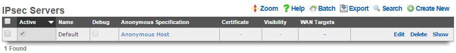
IPsec Server
Entries in the IPsec Server scaffold define configuration profiles for the rXg integrated IPsec server.
The active field enables an option set. Exactly one option set may be active at any time. Enabling a particular option set will automatically disable another existing active option set.
The name field is an arbitrary string descriptor used only for administrative identification. Choose a name that reflects the purpose of the record. This field has no bearing on the configuration or settings determined by this scaffold.
The Pre-Shared key and Certificates fields are used to configure the certificates or pre-shared key that will be used for authenticating IPsec tunnels that use this IPsec specification. The operator may choose to use one or more certificates or a pre-shared key but not both. If one or more certificates are chosen, then the node at the other end of the IPsec tunnel must have the matching private key. If a pre-shared key is chosen, then the node at the other end of the IPsec tunnel must have the exact same pre-shared key programmed.
The anonymous specification field selects the credential and encryption settings for anonymous IPsec connections (i.e., where the client's originating IP address is unknown). Pre-shared-key authentication may not be used for anonymous connections. An anonymous IPsec client must authenticate using a certificate. The certificates to be used by the anonymous clients should be configured in the IPsec Specifications scaffold for the selected anonymous specification. It is critically important to ensure that the settings in the chosen anonymous specification match those of the IPsec client.
The certificate field specifies an alternate certificate to configure the IPsec server with.
By default, access to rXg services are either limited to the LAN or disabled entirely. In certain cases, the operator may desire to permit accessibility to services over the WAN and/or LAN. To enable access to rXg services over the WAN, the operator should specify one or more WAN targets containing the list of allowed hosts and then set the visibility appropriately. If no WAN target is specified and WAN visibility is enabled, any node on the WAN may connect to the service. It is highly recommended that this wide-open configuration be avoided to ensure system security. If LAN visibility is included then all authenticated nodes on the LAN may access this service.
The note field is a place for the administrator to enter a comment. This field is purely informational and has no bearing on the configuration settings.
Site-to-site IPsec VPN Configuration
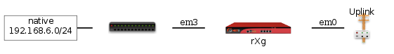
Site-to-site IP-sec VPNs enable devices that are behind VPN concatenators to communicate with each other securely without any configuration changes to the end-user devices. In most cases, site-to-site IPsec VPNs are deployed with privately addressed end-user devices behind the VPN concatenators. Without a site-to-site IPsec VPN, the privately addressed devices would not be able to initiate communication with each other due to the one-way nature of network address translation. Consider the following network diagram:

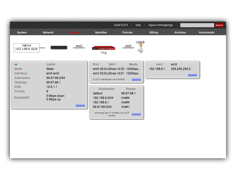
In this example, we have two rXgs and we desire to create a site-to-site IPsec VPN to enable two way communication for devices that are on private addresses behind the rXgs. We will call the rXg on the left with WAN IP 66.67.68.2 east and the rXg on the right with WAN IP 55.45.35.2 west. The network dashboard of the_east_ rXg is shown below:
The rXg IPsec VPN feature is compatible with a broad spectrum of IPsec implementations. It is not necessary for a site-to-site VPN to be established between two rXgs. We have used two rXgs in this example so that we can best illustrate the appropriate configuration for either end of the site-to-site VPN. The network dashboard of the_west_ rXg is shown below:
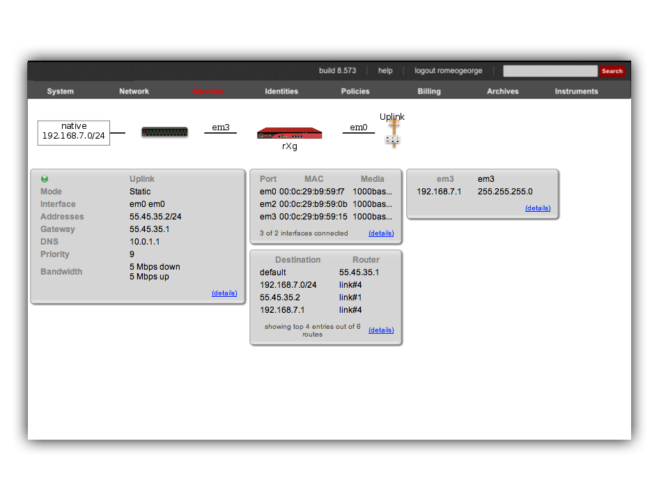
Notice that both rXgs have a single private LAN block associated with them. The east rXg has 192.168.6.0/24 behind it and the west rXg has 192.168.7.0/24 behind it. When configuring IPsec VPNs, it is critically important to ensure that the networks behind the various endpoints of the IPsec VPN do not intersect. This is because IPsec depends on a valid L3 (routing layer) configuration in order to operate.
Establishing a site-to-site VPN is simply a matter of creating a single record in the IPsec Tunnel scaffold on both ends of the connection. The remote gateway field must be set to the IP address of the concatenator on the other end of the site-to-site VPN. The remote networks field must contain the CIDR of the block present on the other end of the site-to-site VPN.
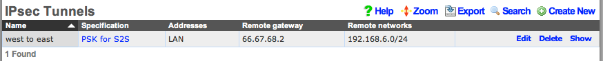
Following our example, the IPsec tunnel record on east(which has WAN IP address 66.67.68.2, LAN address 192.168.6.1 / 24) must have the following settings:
- remote gateway - 55.45.35.2
- remote networks - 192.168.7.0/24
Below is a screenshot of the configuration that is present on east:

Similarly, west (which has WAN IP address 55.45.35.2, LAN address 192.168.7.1 / 24) must have the following settings in the IPsec tunnel record:
- remote gateway - 66.68.67.2
- remote networks - 192.168.6.0/24
Below is a screenshot on configuration that is present on west:
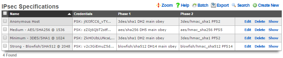
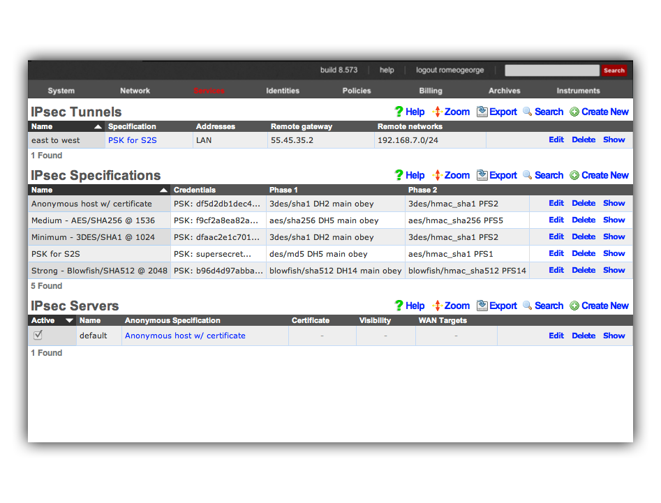
Notice that the IPsec Tunnel records depend on the existence of an IPsec Specification record in order to configure the encryption protocol and keys for the tunnel. In the configuration screenshots shown above, we seen that the specification is referenced as PSK for S2S. A screen shot of the configuration for_PSK for S2S_ that is present on both east and _west_is shown below:
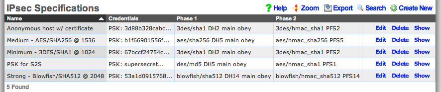
Since we are configuring a site-to-site VPN, we are assuming that both ends of the connection are controlled by trusted parties. Thus we will use a pre-shared key to secure the connection. To accomplish this, we will create a new record in the IPsec Specifications scaffold on both the east and west rXgs. To get a site-to-site IPsec VPN up and running, the individual choices for the encryption protocol and credentials are not as important as the simple fact that they must be exactly the same on both machines. Using a strong pre-shared key is obviously a prerequisite to maintaining the confidentiality and integrity of the VPN.
Several templates are provided as examples for strong, medium and minimum security configurations. The minimum security configuration is the least secure against brute force attacks but is the most compatible. The template for the most secure setting will only function with KAME derived IPsec stacks such as the ones present in OpenBSD and FreeBSD. For more information on the precise meaning behind each of the settings, we recommend reading information that may acquired via a search on IPsec. When configuring a site-to-site VPN, keep in mind that even the slightest difference in a single setting will prevent the site-to-site IPsec VPN from initializing.
For your reference, the complete IPsec configuration for both_east_ and west is shown below:
Once we have this configuration in place on both east and_west_, devices on the 192.168.6.0 / 24 private network behind_east_ may directly contact devices on the 192.168.7.0 / 24 private network behind west and vice versa. Note that absolutely no configuration changes needs to be made on the end-user devices whatsoever. All of the encryption, decryption and routing between the private networks is handled by the IPsec VPN endpoints, which in this case are the east and west rXgs.
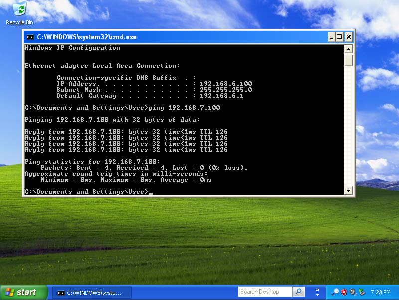
For example, let us assume there is a Windows XP laptop behind_east_. The XP machine will acquire a DHCP address in the 192.168.6.0 / 24 CIDR. Similarly, let us assume there is a Windows 2003 server behind west that is on the 192.168.7.0 / 24 CIDR. Given the site-to-site VPN configuration that we have created on the rXgs, the XP laptop will be able to directly communicate with the Win2k3 server without any configuration changes to the clients.
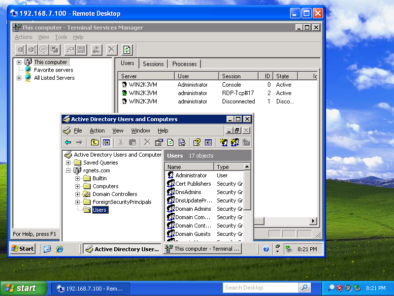
The screenshot below shows the desktop of the Windows XP laptop that is behind east. It has acquired address 198.168.6.100 / 24 from the east rXg. Notice that it can ping the private address 192.168.7.100 directly. The 192.168.7.100 address is configured on the Windows 2003 Server that is behind the _west_rXg.
No configuration changes were made to the Windows XP laptop whatsoever. The Windows XP laptop has no knowledge that the 192.168.7.100 is behind the west rXg. The 192.168.7.100 could be on the other side of the world and the XP laptop would not know any better. Furthermore, the XP laptop does not do any encryption or decryption of traffic. It merely sends traffic to the east rXg which does all of the work in encrypting and forwarding the traffic to the west router for delivery to 192.168.7.100.
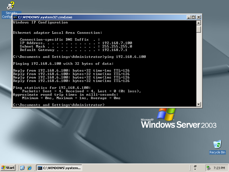
The screenshot below shows the desktop of the Windows 2003 Server that is behind east. It has an address of 198.168.7.100 / 24 which is behind the west rXg. Notice that it can ping the private address 192.168.6.100 directly. As depicted in the previous screenshot, the 192.168.6.100 address belongs to the Windows XP laptop behind the east rXg.
The Windows 2003 Server has no knowledge about the site-to-site IPsec VPN. The Win2k3 server simply forwards packets to the_west_ rXg which does all of the work involved in the encryption and routing of packets to 192.168.6.100 via east.
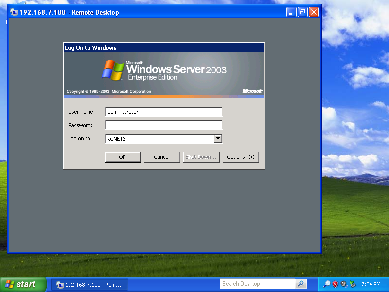
The site-to-site IPsec VPN enables routing between private networks to occur over the public Internet that is otherwise not possible. Once established, any network application may be used. In the screenshots below, the Windows XP client on 192.168.6.100 behind east_is shown initiating and utilization a remote desktop connection to manage the Windows 2003 Server on 192.168.7.100 behind _west.

Site-to-site IPsec VPNs enable RGN operators to have secure remote access to all of their various networks. Any devices that is on a private network behind an rXg may be accessed as if it is a local device at the other end of the site-to-site VPN without any configuration changes to the devices themselves. The possibilities of what site-to-site IPsec VPNs may be used for is limitless. Many RGN operators deploy site-to-site VPNs for remote access as demonstrated above. Another frequent use of site-to-site VPNs is for monitoring. For example, site-to-site VPNs may be used to enable a central site to have a single network monitoring system (NMS) or element monitoring system (EMS) to monitor multiple remote networks.
Host-to-site IPsec VPN Configuration
Host-to-site VPNs are used with the rXg to securely route data between a specific end-user device and the rXg. Host-to-site VPNs may be initiated to the rXg from the WAN or the LAN. The process and technical steps of creating either a WAN to rXg or LAN to rXg host-to-site VPN are identical. However, the use case and business reasons for using the two topologies are radically different.

If the end-user device is on the WAN-side of the rXg, a host-to-site VPNs is usually deployed for the purpose of remote access to local privately addressed machines similar to a site-to-site VPN. However, a host-to-site VPN obviates the need to deploy and configure a VPN concatenator on the end-user network.
A WAN host-to-site VPN is the appropriate methodology to use with a mobile client used by a network administrator that requires access to privately addressed resources when the mobile client must connect to networks which the administrator does not control. For example, if the mobile client uses a wireless WAN connection (e.g., cellular 3G), it would be more difficult to install a VPN concatenator for site-to-site VPN than it would be to configure the device for host-to-site VPN. The use of host-to-site VPNs is ubiquitous in enterprise networks to the extent that even mobile phones operating systems such as Symbian, Windows Mobile and Apple iPhone OS are capable of initiating host-to-site VPNs.

Host-to-site VPNs originating from the LAN-side of the rXg are typically deployed as a facet of revenue generation for the operator. Popular media has helped educate most end-users to understand that there are many security issues present when computer networks are used. This effect may be exploited by RGN operators for the purpose of generating additional revenue by offering security related premium services.
For example, if the LAN distribution mechanism is wireless, a host-to-site IPsec VPN upgrade may be offered to end-users to provide confidentiality and integrity to the traffic over the wireless portion of the Internet link. Enabling the anonymous IPsec VPN capability and integrating the generation of a client certificate into the rXg captive portal allows operators to enjoy zero operator intervention provisioning of host-to-site VPNs.
Host-to-site IPsec VPNs typically use public key cryptography in order to authenticate the initiating hosts. Each initiating host must have a unique keypair in order to ensure the confidentiality and integrity of the IPsec VPN connection. In addition, the IPsec VPN concatenator must identify itself with a keypair to the initiating client. The rXg uses X.509 certificates and private keys for the purposes of authenticating both ends of a host-to-site IPsec VPN.

The rXg expects that the operator has stored certificates for each of the hosts that will be initiating a host-to-site IPsec VPN in the certificates scaffold on the certificates view. When a host-to-site IPsec VPN connection is initialized, the rXg expects that the initiating client will authenticate by using the matching private key to sign an authentication credential. Similarly, the rXg must be configured with a private key and certificate for authenticating the site. The initiating client is assumed to have a copy of the rXg certificate and the rXg will sign an authentication credential with the matching private key.
The certificates view of the rXg administrative console may also be used to create keypairs that may be used for authenticating host-to-site IPsec VPNs. To accomplish this, use the certificate authorities scaffold to create a new authority that can be used to sign certificate signing requests to fully populate certificates. For more information, please see the documentation on the certificates view.
In order to instantiate a host-to-site IPsec VPN, configuration changes must be executed on both the rXg and the end-user device. However, the same process is used to configure the end-user device and the rXg to enable a host-to-site IPsec VPN concatenator regardless of whether the VPN will be initiated from the WAN or LAN. Let us consider the east rXg that was discussed earlier. The configuration and network diagram for the east rXg is shown below:
The rXg must be configured to allow anonymous connections to enable the host-to-site IPsec VPN capability. To accomplish this, an entry in the IPsec servers scaffold must be created that specifies the site authentication certificate. The IPsec server record must be linked to a IPsec specification record that defines the encryption protocol as well as the client certificates that will be accepted for connection initiation.
The configuration steps of the end-user device needed to setup a host-to-site VPN follow the same pattern regardless of the operating system of the end-user device. At a bare minimum, the following items need to be configured in order for a host-to-site IPsec VPN to be established:
- host certificate
- host private key
- IP address of VPN router
- remote network CIDR
- encryption protocol and associated parameters The precise steps that are needed depend on both the operating system as well as the VPN client software. Many popular operating systems have "bare metal" VPN clients built into them that are suited for operation by IT professionals. However, in almost all cases, user friendly VPN client GUIs are available from both free and commercial sources.
The IPsec capabilities of all recent versions of Microsoft Windows is configured using the Microsoft Management Console. Depending on the specific of Windows, the MMC snap-in will be called something like "IP Security Policy Management" or "Windows Firewall with Advanced Security." Search the web for Microsoft'sstep by step guide to deploying Windows firewall and IPsec policies and review pages 15-17 as well as 89-91 for specific instructions. For those who are less technically inclined, we have that the Greenbow VPN client greatly simplifies the creation of host-to-site IPsec VPNs on Windows.
The MacOS X operating system incorporates numerous open source components into its IPsec VPN stack. This makes the MacOS X IPsec VPN one of the most compatible of the commonly available commercial offerings. However, the command line configuration is needed to setup the IPsec stack for the vast majority of use cases. For this reason, we recommend that users download and install the IPsecuritas freeware GUI to configure host-to-site IPsec VPNs between MacOS X clients and rXgs.
Example OpenVPN Configuration
- Create certificate
- Create Networking
- Configure OpenVPN in rXg
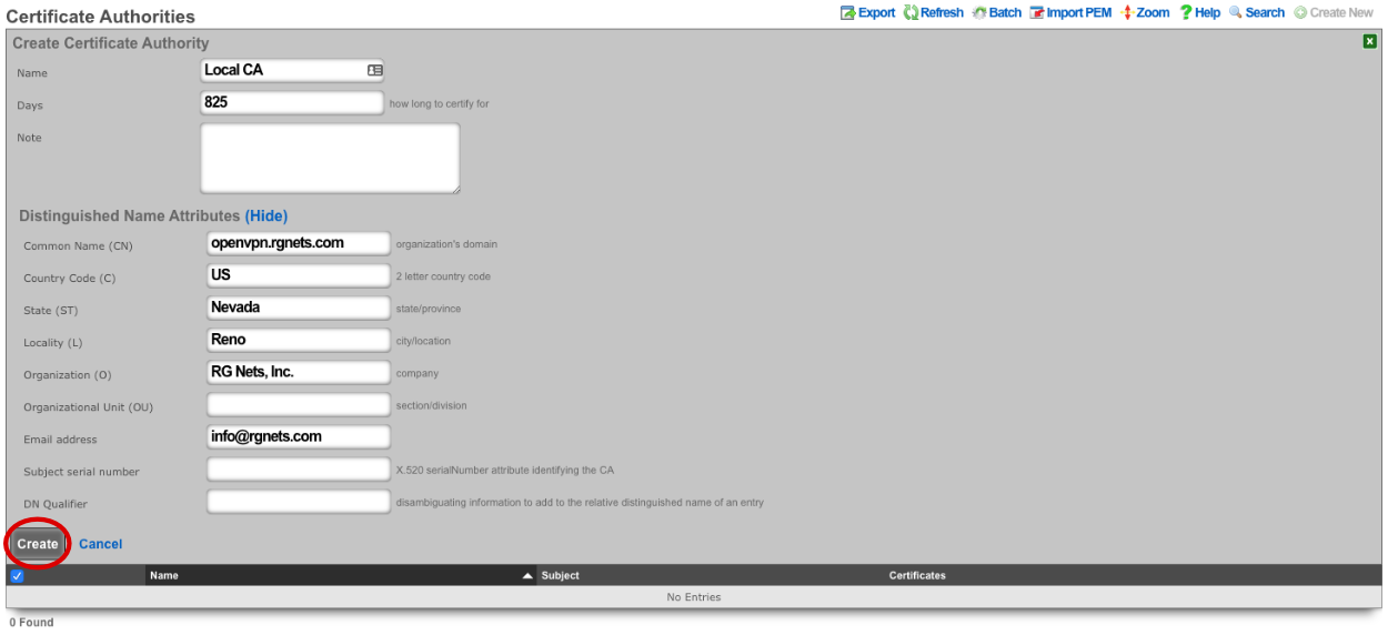
Navigate to System-->Certificates. If there are no Certificate Authorities we will need to create one to self sign our OpenVPN certificate. Click Create New on the Certificate Authorities scaffold.

Name is arbitrary and be set to anything. Days by default will be 825. Common Name does not need to resolve for the purposes of using OpenVPN. Fill out the remaining fields with the appropriate information for your location. Click Create.
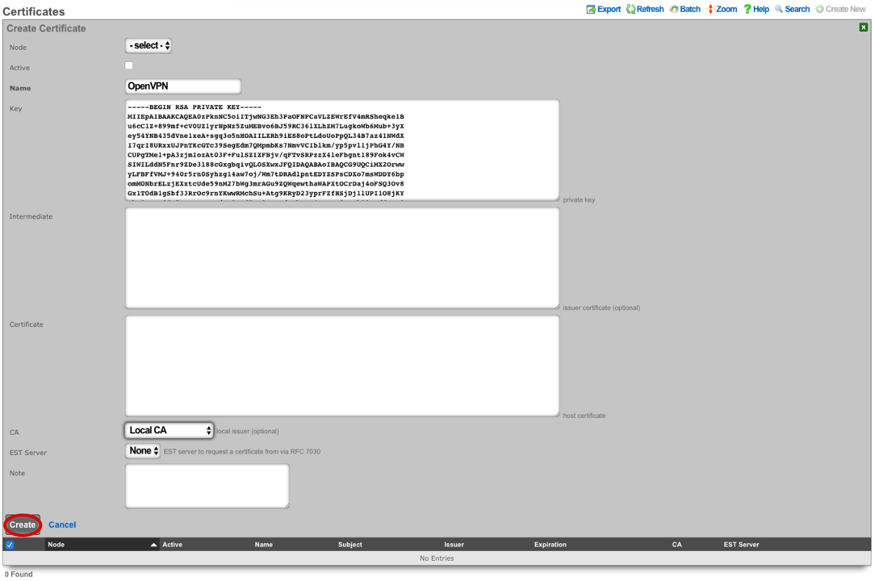
Next create a new Certificate.

For the certificate only the name needs to be entered at this step. Verify CA is set to Local CA. Click Create.
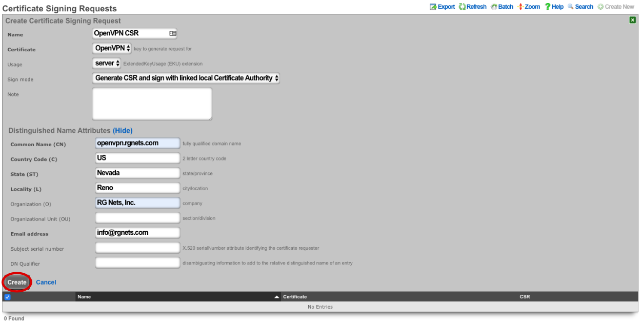
Next create a new Certificate Signing Request.

Verify that the Certificate field is set to the correct certificate. Sign mode should be set to Generate CSR and sign with linked local Certificate Authority. Common Name should match the Common Name in the Certificate Authority. Fill out the remaining fields with the appropriate information if applicable. Click Create.
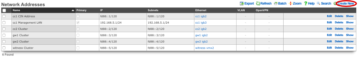
Next we need to create the networking that will be used for devices connecting to the OpenVPN. Navigate to Network-->LAN, and create a new Network Address.
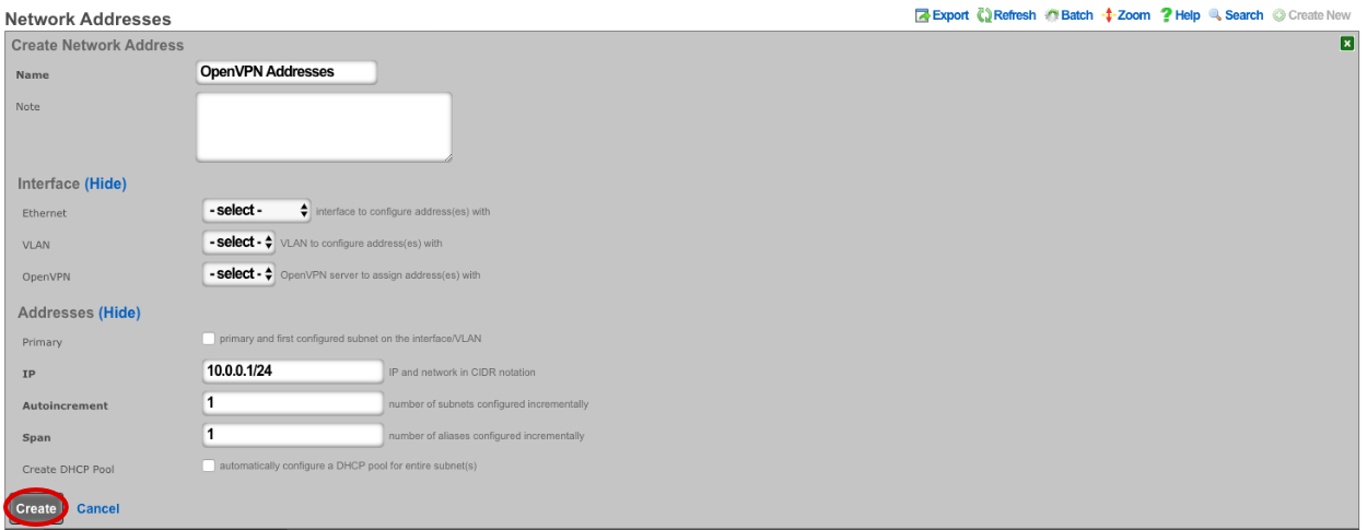
Enter a name. Make sure that Interface is set to -select- for each box. The IP field will be the addresses available to devices connecting via OpenVPN and should be entered in CIDR notaton. Autoincrement and Span should be left set to 1, do not check Create DHCP Pool. Click Create.
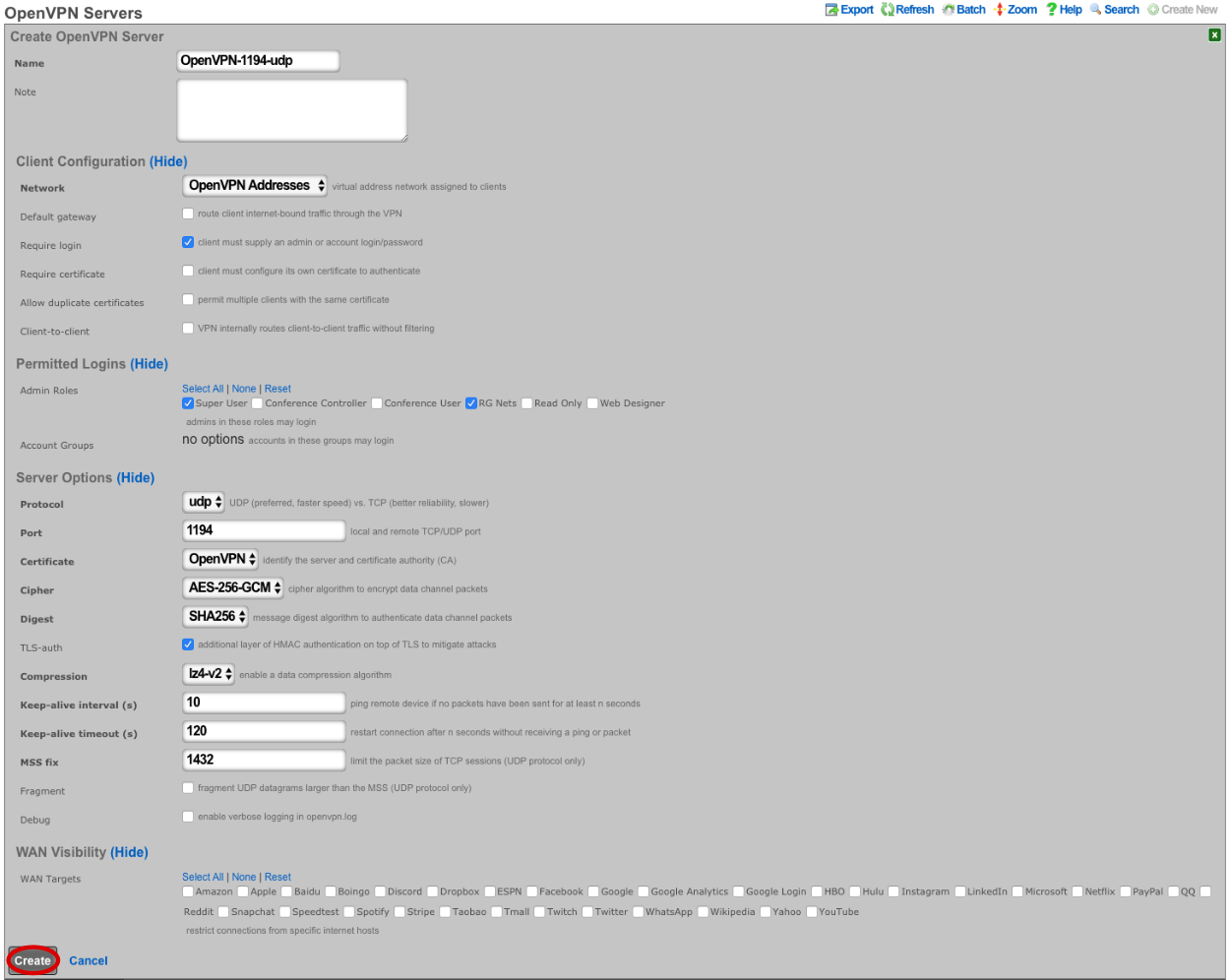
Navigate to Services-->VPN and create a new OpenVPN Server.

Enter a name, or use the default. Under Client Configuration Network should be set to the Network Addresses we created earlier. If you want traffic to route through the remote system check the Default gateway option. Require login is checked by default and this prevents access except for Admin Roles we have selected in this example. Server Options will be left at their default values for this example. WAN Targets can be selected to further restrict access if desired. Click Create.
Now the config can be downloaded from the rXg and imported into a VPN client of choice.

## WireGuard VPN
WireGuard is a modern, lightweight VPN protocol known for its simplicity, speed, and strong cryptography. It uses public key authentication and runs in the Linux \ FreeBSD kernel for high performance, though it is also available on Windows, macOS, Android, and iOS. Configuration is minimal, often requiring just a few lines per peer. WireGuard establishes encrypted tunnels between devices, routing selected IP traffic securely. It is ideal for both personal VPNs and site-to-site secure networking.
The WireGuard configuration involves the rXg-side configuration (WireGuard server) and the client side configuration (WireGuard client).
### WireGuard server (rXg) configuration
The WireGuard server configuration features two steps, i.e.,
creating a WireGuard pseudointerface in the
System::LAN::Pseudo Interfacesscaffoldcreating at least one WireGuard client (tunnel) in the
Services::VPN::WireGuard Tunnelsscaffold and then transfer this configuration to the client side usign the QR code or the configuration file download
In order to create a WireGuard pseudointerface, click the Create New button in the System::LAN::Pseudo Interfaces scaffold and fill in the following parameters:
Nameof the pseudointerface interface, comprising an arbitrary string descriptor used only for administrative identification. Choose anamethat reflects the purpose of the record. This field has no bearing on the configuration or settings determined by this scaffold.Interface type: select theWireGuardtypethe
WireGuard port,WireGuard private key, andWireGuard public keyare best left to their default values, though may be modified as needed. TheWireGuard portdesignates the remote TCP/UDP port used for WireGuard communications, while theWireGuard private keyandWireGuard public keyare used for authentication purposes between the remote client and the server.the
IP Configurationsection allows to select one of the already existing local IP interfaces created on the rXg (using theAddressesentry) or create a new IP interface specifically for WireGuard purposes (using theWireGuard IPentry)
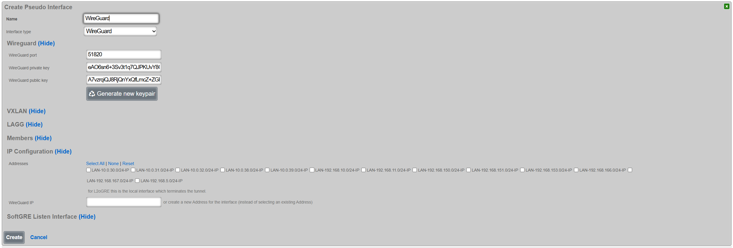
Once created, the pseudointerface is then displayed under the respective scaffold, as shown below:

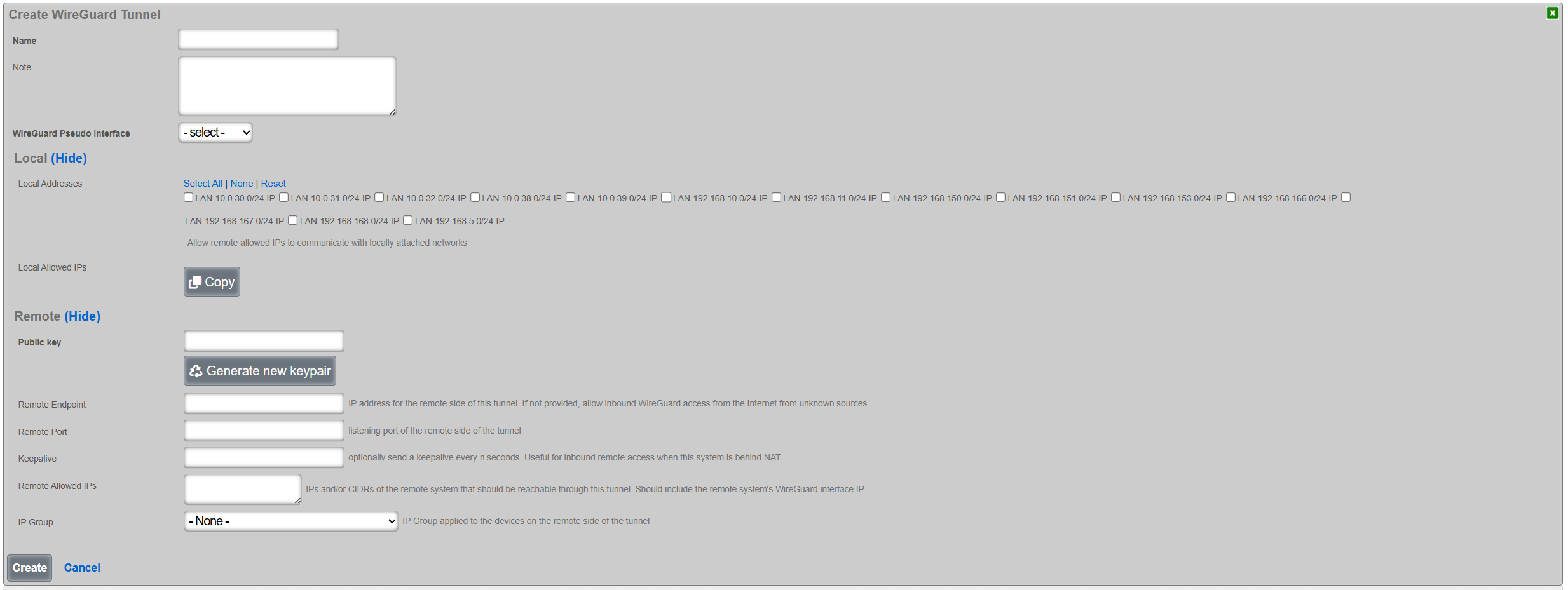
Once the WireGuard pseudointerface is created, at least one WireGuard tunnel needs to be created using the Services::VPN::WireGuard Tunnels scaffold, filling in the following parameters:
Nameof the WireGuard tunnel, comprising an arbitrary string descriptor used only for administrative identification. Choose anamethat reflects the purpose of the record. This field has no bearing on the configuration or settings determined by this scaffold.WireGuard Pseudo Interfaceallows to select one of the WireGuard pseudointerfaces already created on the given rXg systemLocal Addressesallows to (optionally) select at least one of the existing IP groups that will be permitted to communicate with devices across the WireGuard tunnelPublic keyandPrivate keyis the WireGuard tunnel public / public key pair for authentication purposes, which is generated using theGenerate new keypairbutton.Remote Endpointand theRemote Portrepresent the IP address / TCP/UDP port tuple for the remote side of the WireGuard tunnel instance. If not filled in, the given WireGuard tunnel permits access from any source IP / port tuple, making the WireGuard tunnel effectively open to public Internet. If filled in, the WireGuard tunnel will accept traffic only from the given source IP address and the given source TCP/UDP port, rejecting any other traffic.Remote Allowed IPsdescribes which remote IP prefixes are reachable across the given WIreGuard tunnel. Make sure that the IP prefixes on the local rXg system and IP prefixes across the WireGuard tunnel do not overlap. For WireGuard tunnel configuration for a single client (e.g., a laptop, a smartphone), this field is expected to contain a host prefix (/32) assigned to the given target device.IP Groupdesignates the IP Group applies to traffic originating across the WireGuard tunnel. This selection is optional.
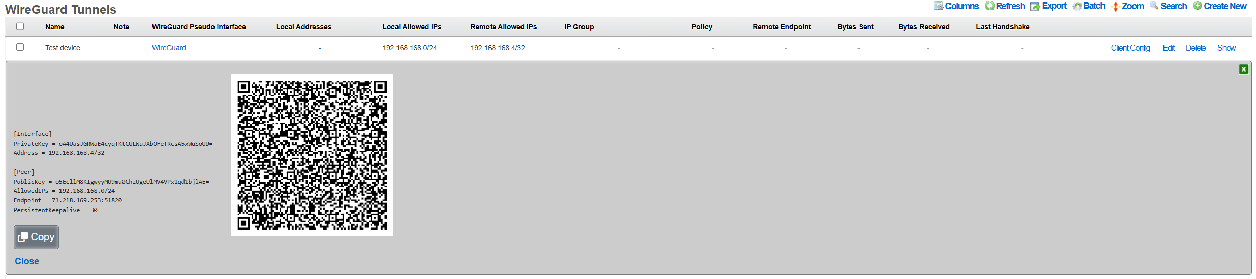
Once created, the tunnel is then displayed under the respective scaffold, as shown below:

The configuration for the given tunnel can be then displayed using the Client Config::View Config menu, as shown below. A QR code and a textual representation of the client (tunnel) parameters is displayed. The QR code can be used to conveniently apply the configuration to client devices, e.g., a smartphone, laptop, etc.
The WireGuard tunnel configuration can be also exported using the Client Config::Download Config menu, and then transfered to the target client and uploaded to the local WireGuard application.
### WireGuard client configuration
The client configuration is highly dependent on the platform being used by the customer. The following two examples show the use of the WireGuard tunnel configuration on an Android smartphone and an Apple laptop.
#### Android smartphone
Open the official WireGuard Android application and select the + symbol in teh bottorm right hand corner of the screen.
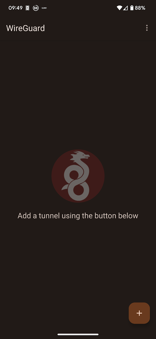
Select the Scan from QR code or Import from file or archive, depending on the preference. There is also an option to Create from scratch and add specific configuration elements manually. If the QR code-based or the file import-based method was selected, name the newly imported tunnel configuration
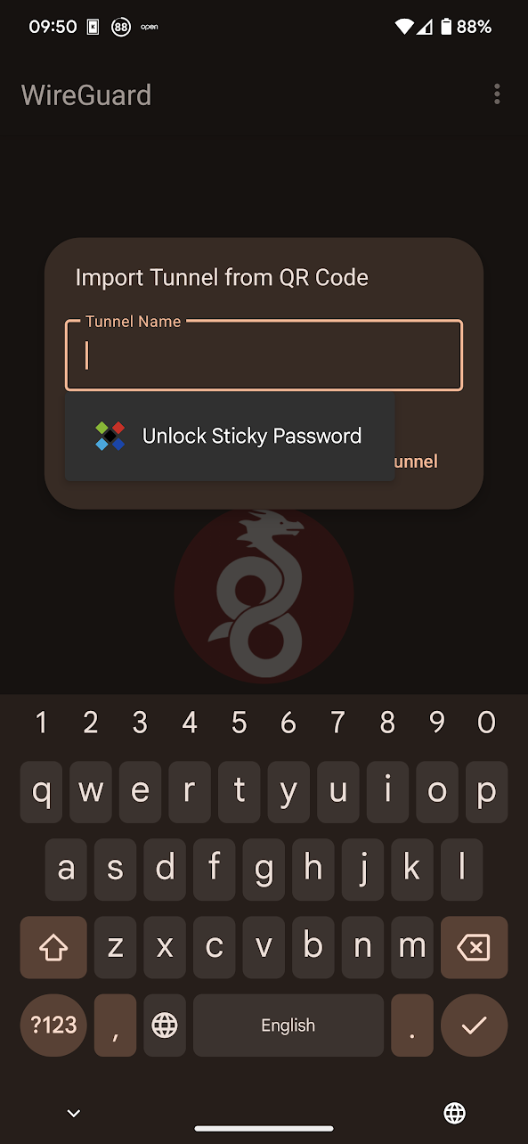
and the WireGuard tunnel configuration is then imported and ready to use.
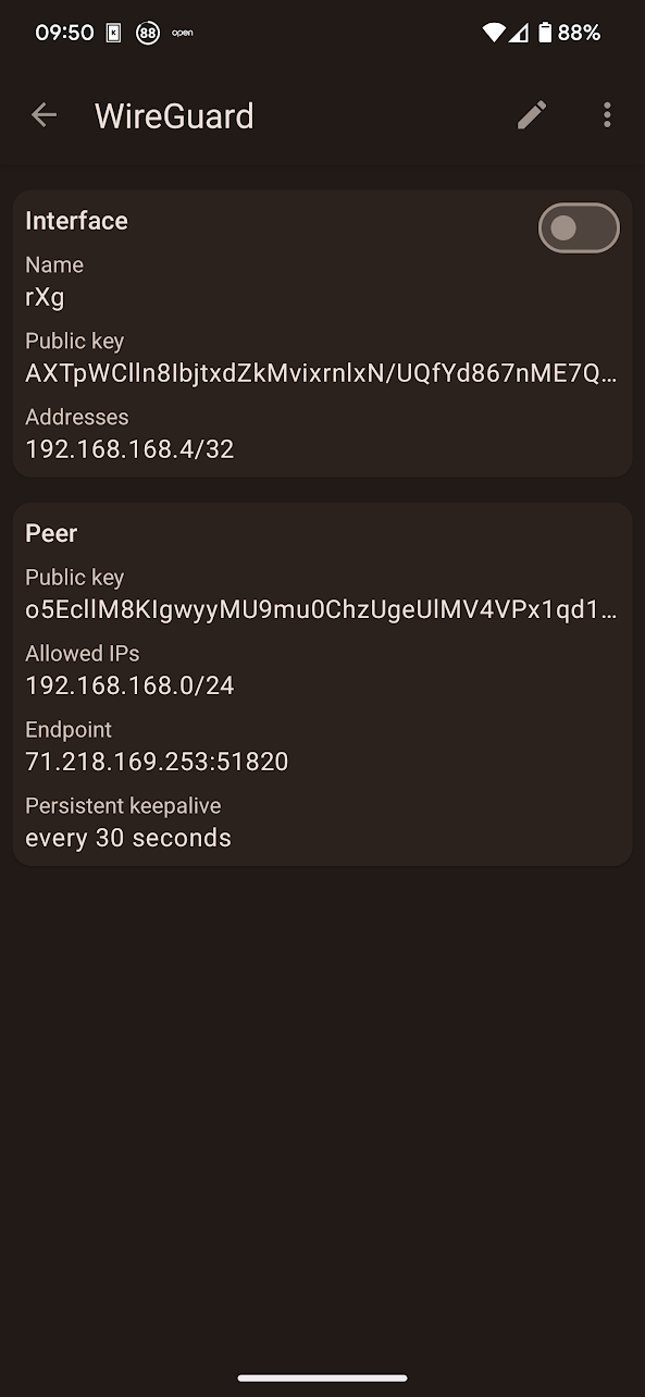
Toggle the Interface button and the tunnel will come online, with bytes sent/received incrementing on the rXg side, and the Latest Hanshake field indicating the time when the latest communication hanshake was completed.

#### Apple laptop
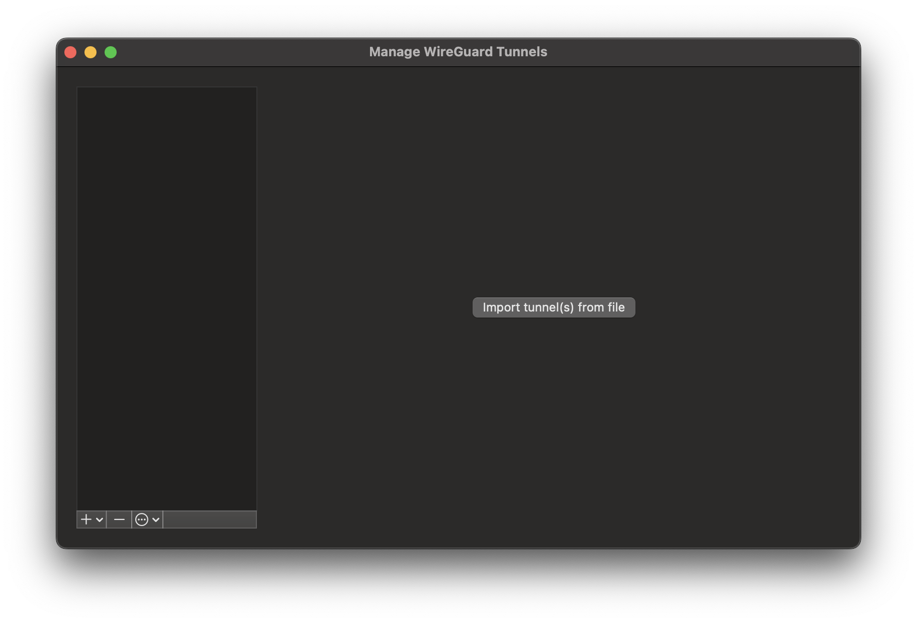
Open the official WireGuard Apple application and select the Import tunnel(s) from file symbolin the middle of the screen. Note that the import via QR code is not supported in the laptop / desktop version of the WireGuard client.
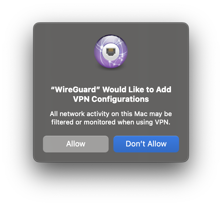
Select the *.conf file (extension is critical, the WireGuard Apple application will not permit the selection of any other files) and confirm the VPN tunnel is indeed intended to be created.
Once confirmed, the tunnel configuration is imported and can be activated using the Activate button. There is also an on-demand option, which triggers the WireGuard tunnel when and if specific select destinatio is identified.
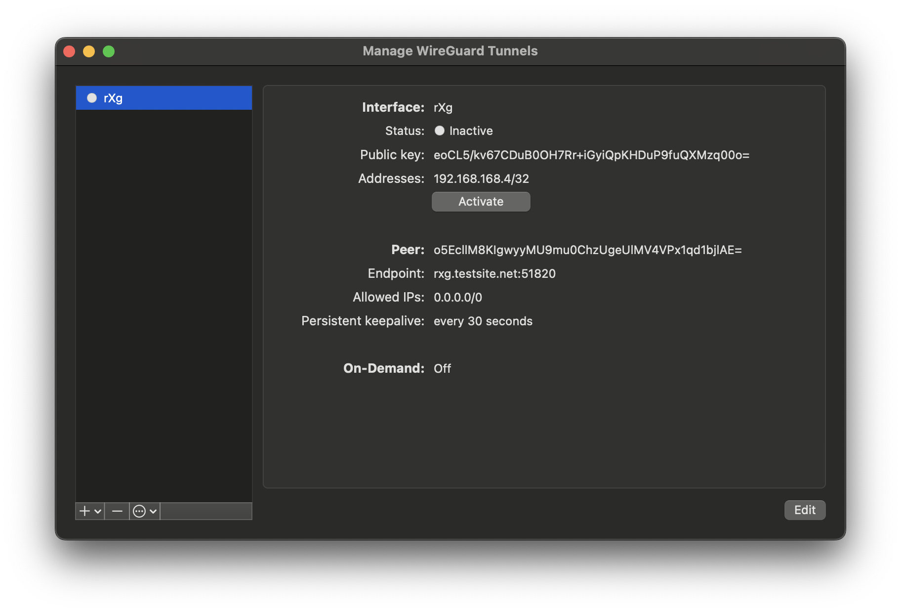
Toggle the Activate button and the tunnel will come online, with bytes sent/received incrementing on the rXg side, and the Latest Hanshake field indicating the time when the latest communication hanshake was completed.
IPv6 IPsec Support
The rXg IPsec implementation provides comprehensive support for IPv6 in addition to IPv4:
IPv6 Site-to-Site Tunnels
IPv6 site-to-site IPsec tunnels operate identically to IPv4 tunnels with the following considerations:
- Remote Networks: Specify IPv6 networks in CIDR notation (e.g.,
2001:db8:1::/64) - Mixed Protocol Support: A single tunnel can carry both IPv4 and IPv6 traffic by specifying both types of networks
- Gateway Addressing: Remote gateways can be IPv6 addresses or dual-stack hostnames
IPv6 Host-to-Site (Anonymous) VPN
Anonymous IPsec clients can connect over IPv6 and receive IPv6 address assignments:
- IP Pools: Configure IPv6 address pools using prefix delegation (e.g.,
2001:db8:vpn::/64) - Dual-Stack Clients: Clients can receive both IPv4 and IPv6 addresses simultaneously
- Policy Integration: IPv6 traffic through IPsec tunnels is subject to the same policy enforcement as IPv4
Configuration Notes for IPv6
- Ensure your uplink interfaces have IPv6 connectivity configured
- IPv6 IPsec tunnels require appropriate firewall rules for ICMPv6 and IPsec protocols
- Consider IPv6 fragmentation issues with path MTU discovery
Advanced Troubleshooting
Debugging IPsec Connections
Enable Debug Logging
- IPsec Server Options: Enable "Debug Mode" in the IPsec Server scaffold for anonymous connections
- Tunnel-Specific Debugging: Monitor logs in
/var/log/messagesfor strongSwan output - Connection Status: Use
swanctl --list-sascommand to view active security associations
Common Issues and Solutions
Tunnel Won't Establish - Verify both ends have matching IPsec specifications (encryption, authentication, DH groups) - Check that Phase 1 and Phase 2 proposals are compatible - Ensure certificates are valid and properly installed - Verify pre-shared keys match exactly (case-sensitive)
Tunnel Establishes but No Traffic Flows - Check that local and remote network ranges don't overlap - Verify routing is correctly configured for tunnel traffic - Ensure firewall rules permit IPsec traffic - Check for conflicting NAT rules
Frequent Disconnections - Adjust DPD (Dead Peer Detection) settings for network conditions - Review lifetime settings for Phase 1 and Phase 2 - Check for NAT timeout issues on intermediate devices
Certificate Authentication Failures - Verify certificate chains are complete - Check that certificate usage flags are set correctly (server vs client) - Ensure CA certificates are installed and trusted - Validate certificate expiration dates
Log Analysis
Key log entries to monitor:
charon: IKE_SA established
charon: CHILD_SA established
charon: authentication of peer failed
charon: DPD detected dead peer
Network Diagnostics
- Packet Capture: Use tcpdump to capture IPsec traffic (ESP/IKE protocols)
- Connectivity Testing: Test basic IP connectivity before enabling IPsec
- MTU Issues: IPsec adds overhead; consider reducing MTU for client connections
Performance Optimization
Encryption Algorithm Selection
For optimal performance, consider the following recommendations:
High Throughput Scenarios: - Use hardware-accelerated AES (AES-NI) when available - AES-128-GCM provides good security with excellent performance - ChaCha20/Poly1305 is ideal for systems without AES hardware acceleration
Low-Power/Mobile Devices: - ChaCha20/Poly1305 offers better power efficiency than AES on mobile CPUs - Consider smaller DH groups (Group 19/ECP-256) for faster key exchange
System Tuning
Network Interface Optimization: - Enable large receive offload (LRO) and transmit segmentation offload (TSO) on interfaces - Tune network buffer sizes for high-throughput scenarios - Consider jumbo frames for site-to-site connections over dedicated links
Strongswan Configuration:
- Adjust threads setting in strongswan.conf for multi-core systems
- Enable load_modular = yes for optimized plugin loading
- Tune rekey timing to balance security and performance
Monitoring Performance: - Monitor CPU utilization during IPsec operations - Track throughput using the IPsec Entries instrumentation - Use system monitoring tools to identify bottlenecks
Scalability Considerations
- Connection Limits: Plan for maximum concurrent anonymous connections
- Certificate Management: Use efficient certificate storage and validation
- Memory Usage: Monitor memory consumption with large numbers of active tunnels
WLAN-IPsec Integration
The rXg supports integrating wireless networks with IPsec for enhanced security:
Automatic IPsec for WLAN Clients
When configured, WLAN clients can be automatically enrolled in IPsec tunnels:
- WLAN Configuration: In the WLAN scaffold, select an IPsec option to associate with the wireless network
- Client Certificate Distribution: Certificates can be automatically distributed to connecting clients
- Policy Integration: WLAN clients using IPsec are subject to the IP group policies associated with the IPsec option
Use Cases
- Public Wi-Fi Security: Automatically encrypt all traffic from wireless clients
- Enterprise WLAN: Provide additional security layer for corporate wireless networks
- Guest Network Isolation: Use IPsec to provide secure guest access with policy isolation
Configuration Steps
- Create an IPsec specification with appropriate encryption settings
- Create an IPsec server option with certificate-based authentication
- Configure the WLAN to use the IPsec option
- Deploy client certificates to connecting devices
API Documentation
The rXg provides REST API access to IPsec configuration and monitoring:
Available Endpoints
IPsec Tunnels (/api/ipsec_tunnels):
- GET: List all configured tunnels with status
- POST: Create new site-to-site tunnel
- PUT/PATCH: Modify existing tunnel configuration
- DELETE: Remove tunnel configuration
IPsec Specifications (/api/ipsec_specifications):
- Full CRUD operations for encryption/authentication specifications
- Supports validation of cryptographic parameters
IPsec Options (/api/ipsec_options):
- Manage anonymous IPsec server configurations
- Control active server option selection
IPsec Entries (/api/ipsec_entries):
- Read-only access to active connection instrumentation
- Monitor connection status, traffic counters, and timing
Authentication
API access requires proper authentication tokens and appropriate administrative permissions. IPsec configuration requires system-level permissions.
Example Usage
# List all IPsec tunnels
curl -H "Authorization: Bearer $TOKEN" https://rxg.example.com/api/ipsec_tunnels

# Get tunnel status and statistics
curl -H "Authorization: Bearer $TOKEN" https://rxg.example.com/api/ipsec_entries

# Create new tunnel
curl -X POST -H "Authorization: Bearer $TOKEN" -H "Content-Type: application/json" \
  -d '{"name":"Branch-Office","remote_gateway":"203.0.113.1","remote_networks":"10.1.0.0/24"}' \
  https://rxg.example.com/api/ipsec_tunnels


