Virtualization
- Virtualization Overview and Getting Started
- Virtualization Deployment Guide
- VM Network Configuration Guide
- VM Snapshot Management Guide
- Virtualization Design Guide
The rXg virtualization platform provides enterprise-grade virtual machine management built on FreeBSD's bhyve hypervisor. This comprehensive solution includes advanced features like cloud-init automation, ZFS-based snapshots, sophisticated network configuration, and robust VM lifecycle management.
Virtualization Deployment Guide
The most common use case of virtualization within the rXg is to cluster multiple rXgs together on the same bare metal machine to maximize the use of available resources. The following steps will guide you through building a virtual infrastructure capable of clustering.
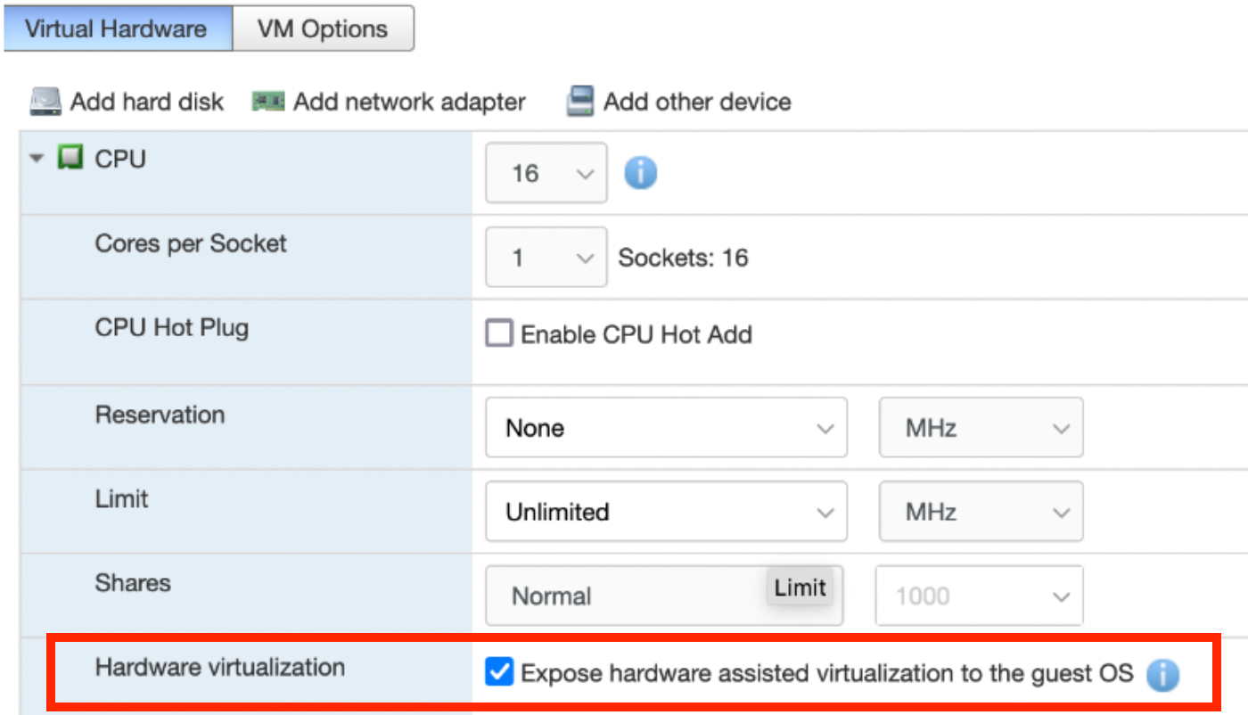
Note: If rXg virtualization host is itself installed onto a virtual machine running on ESXi, ensure that hardware virtualization is enabled in the VM options.
Create a Virtualization Host
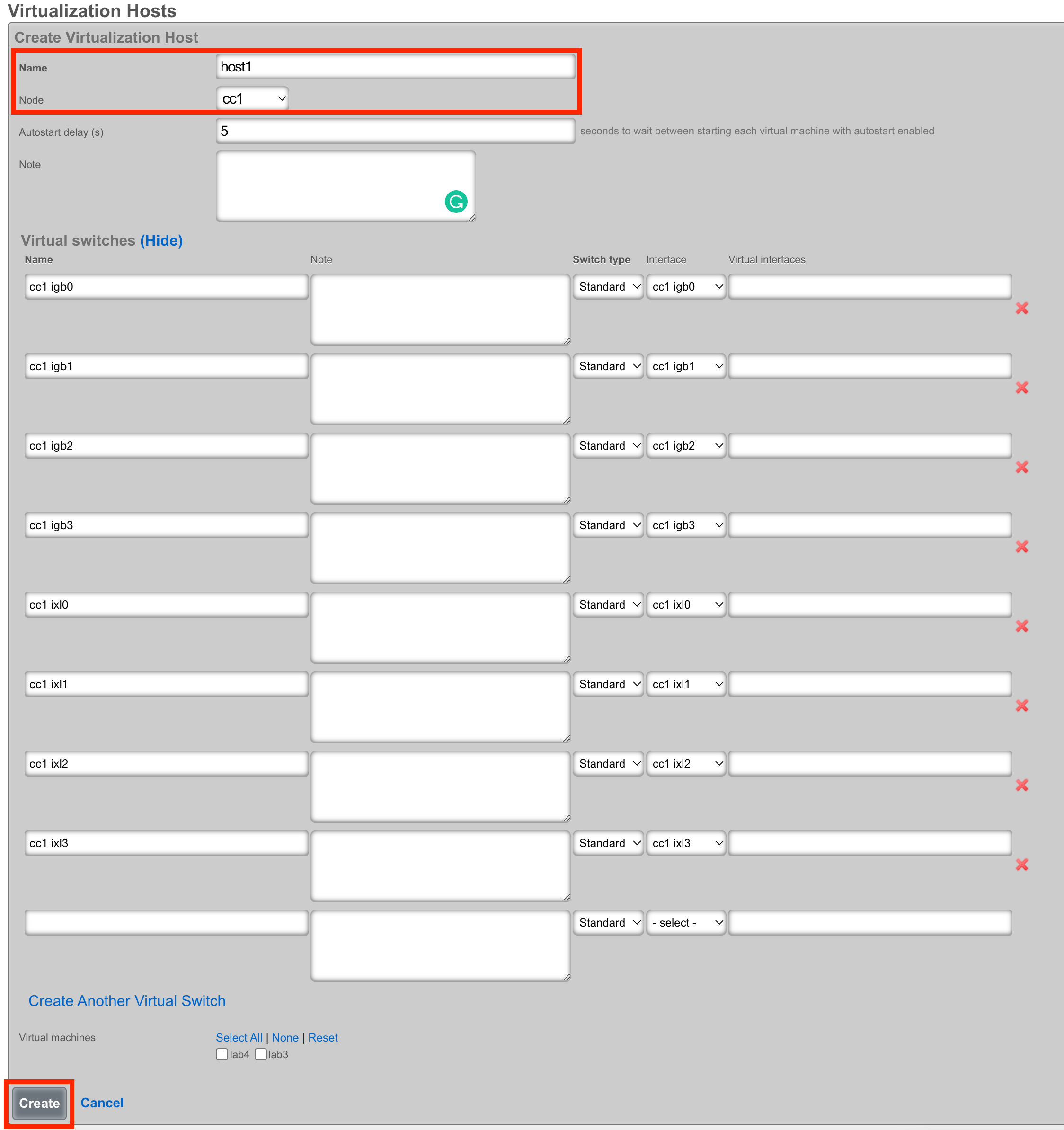
From the Virtualization Hosts scaffold, click Create New

A host can be created on any bare metal node you wish to use as a virtualization environment. Assign the host a name and select the node that will be used for virtualization. The Autostart delay can be left at the default of 5 seconds. You will notice that a virtual switch has already been added for each physical interface on the host. These virtual switches will function whether or not the physical interfaces are connected - you can configure network connectivity using either direct bridge mode (with physical uplink) or routed mode (without physical uplink) as described in the Advanced Networking Architecture section. Click create at the bottom to proceed.
Load the ISO onto the Host
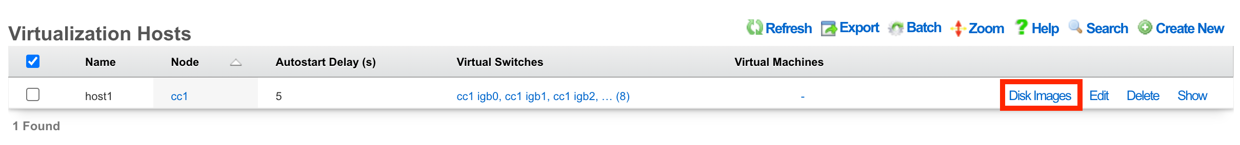
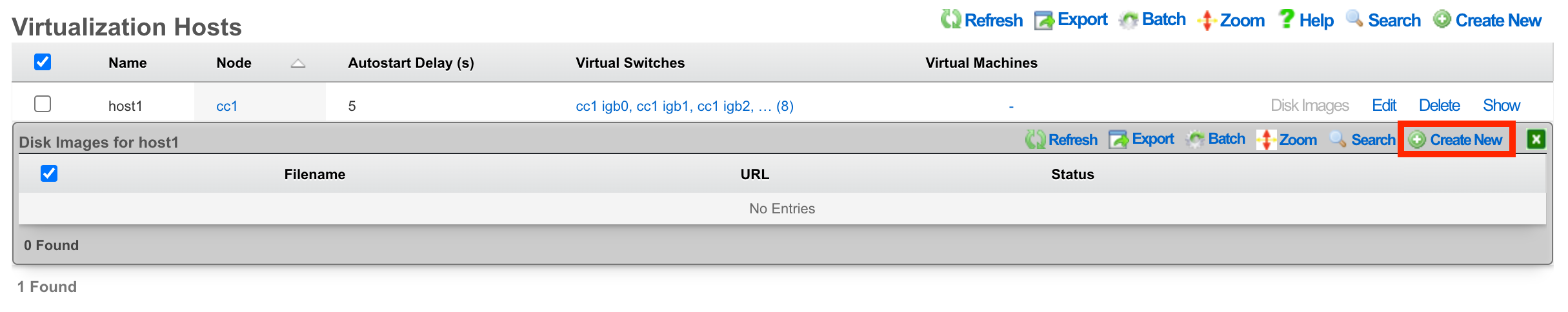
Once the host is created, you can click Disk Images to load the ISO file that will be used as the operating system for your virtual machines.
Next, click Create New.
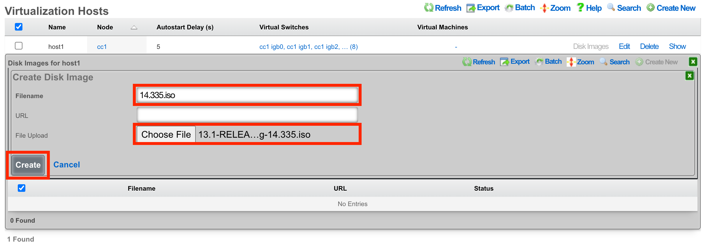
The Filename field is required. This will be used to reference the associated .iso file. The rXg provides two methods to load the .iso file onto the system. You can provide a URL that points to the .iso file, and the rXg will download it directly, or you can use the File Upload method to select an .iso from your local machine to upload to the system.
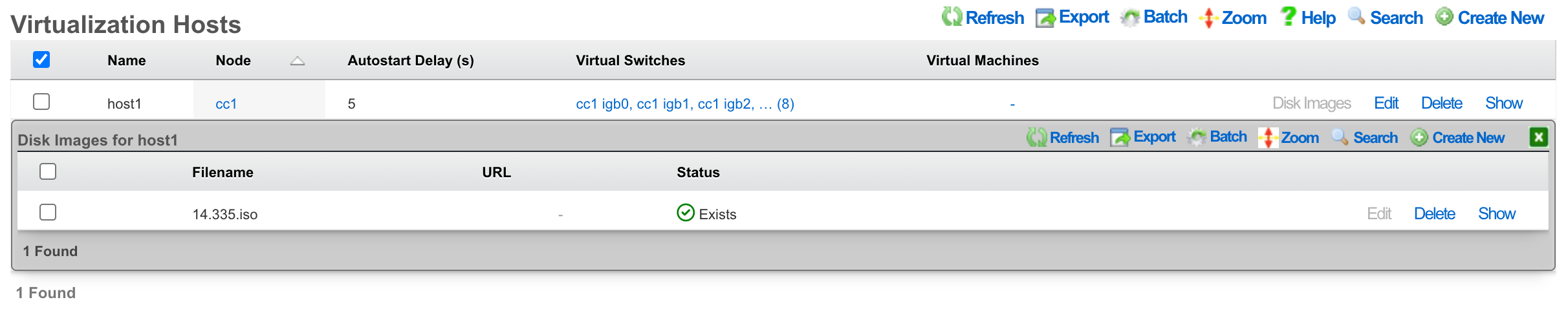
Once the upload/download is complete, you will see the file in the list.
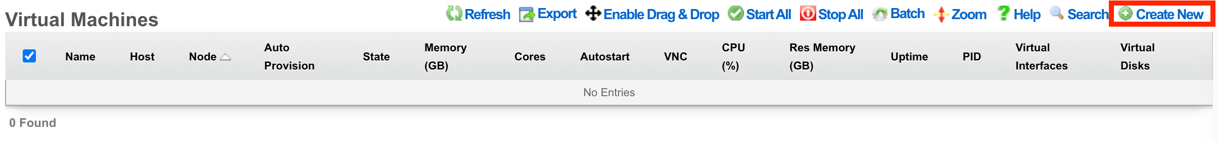
Create a Virtual Machine
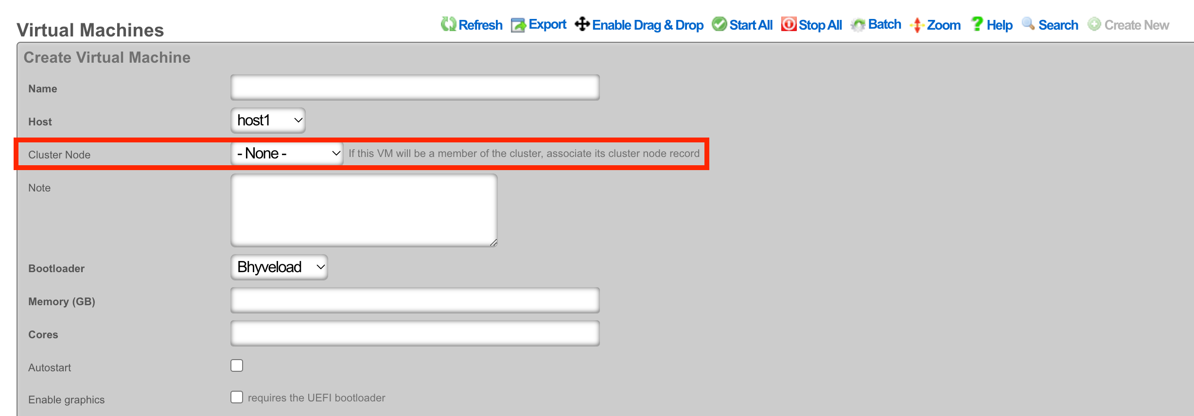
From the Virtualization Machines scaffold, click Create New
Assign the virtual machine a name and select the host that it should be built on.
Cluster Node Auto Provision
If this VM is to be part of a cluster, and the Virtualization Host is the CC, you can use the Cluster Node dropdown to automate the clustering configuration. The rXg will combine the data collected from this form with available information from the CC, create a configuration template, and automatically apply it after the software installation is complete. This process allows the VM to join the cluster automatically.
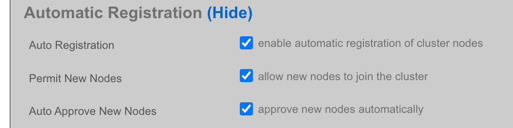
Note: The host CC record (System >> Cluster) will need to be configured for Automatic Registration.
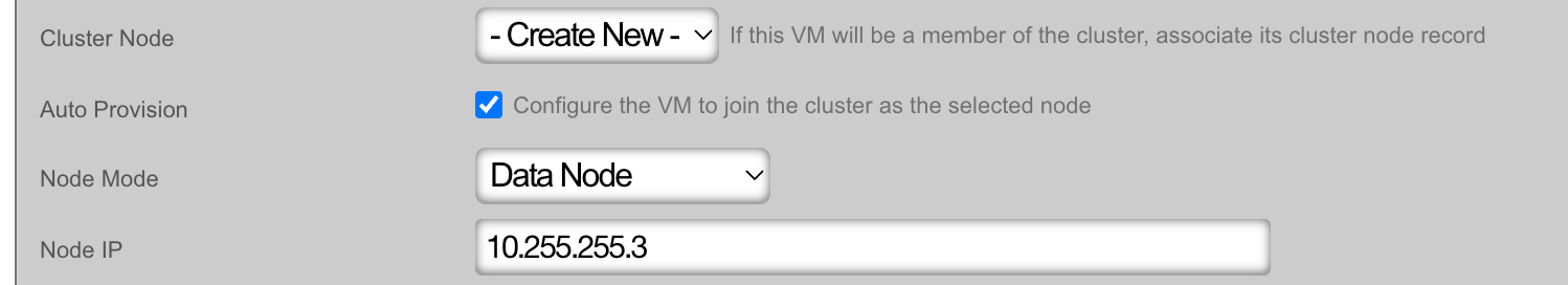
The Cluster Node dropdown will allow you to select an existing cluster node record or create a new one. If you choose an existing record, you need to check the Auto Provision option to activate this feature. All other required information is collected from the current configuration. If you choose Create New, providing the Node Mode and Node IP address will also be necessary.
Create New
Existing Record

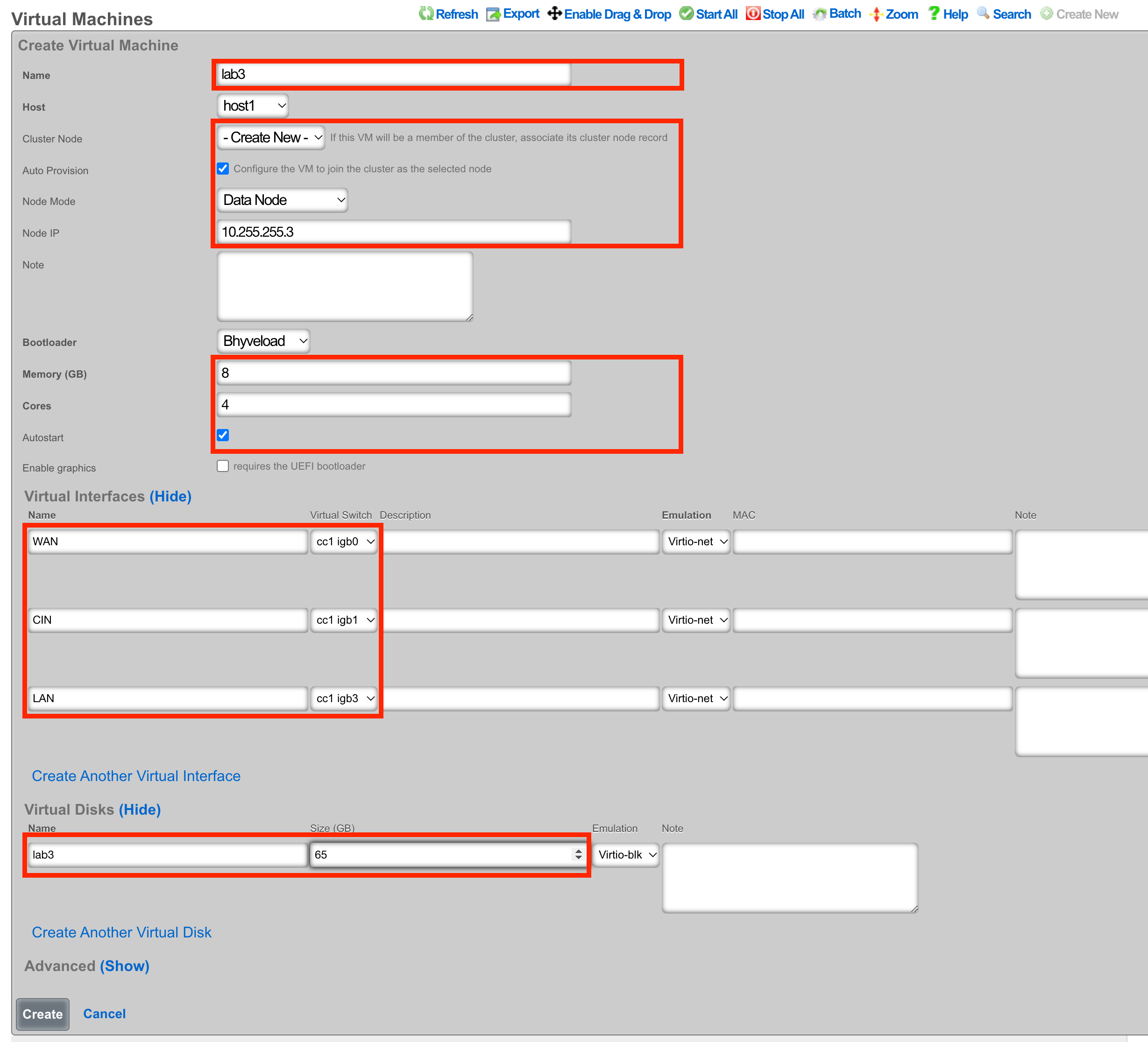
The bootloader can stay at the default setting for the rXg installation. Other operating systems, such as Windows, may require a different bootloader. Set the memory and CPU count as necessary to support the VM that you are creating. It is recommended to enable Autostart so that if the host is power cycled, the guest VM will automatically start back up. Add virtual interfaces as needed and assign them to a virtual switch. In this example, I have created a virtual interface for the WAN, CIN, and LAN and matched them to the physical ports I plan to use on the host. Add a virtual disk to the VM of the appropriate size to support the rXg that you are installing. Adding an additional 20 GB of space is necessary to allow for overhead here. Click Create.
Begin the OS Installation
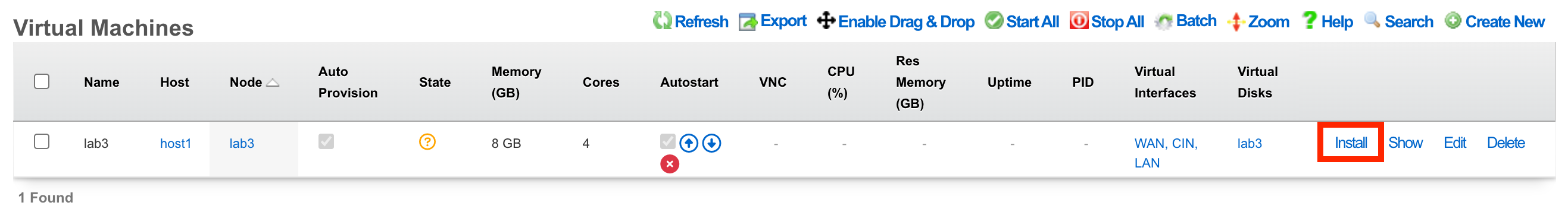
With the VM created, you can click the Install link to select a disk image for installation.
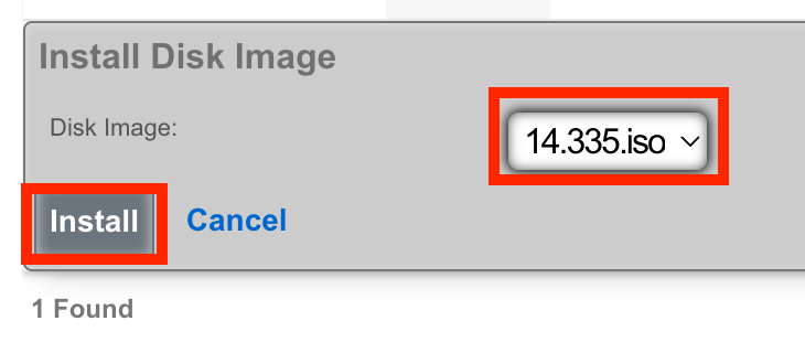
Select the desired image and click Install.
Console Access
The console can be reached via an SSH session to the host node and then switching to the root user.
Type vm console your_vm_name.
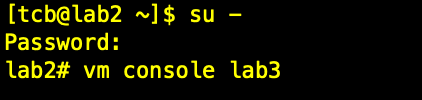
Press Enter
To exit the console session, assuming you were SSH'd to the host, type "~~." You may need to press enter before the first ~ if it doesn't work the first time. (needs to be entered on its own input line)
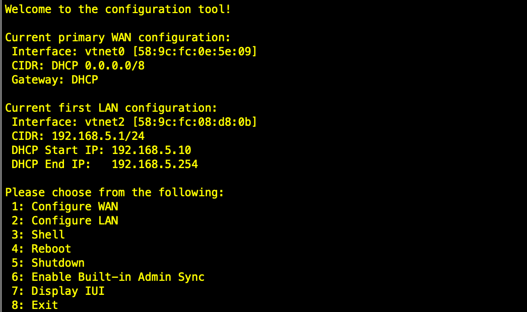
After installation, the node can be configured from the primary CC.
Ubuntu Server VM Installation Example
This section provides a comprehensive walkthrough for creating and configuring a virtual machine to run Ubuntu Server, demonstrating the complete process from initial VM creation through application deployment.
Step 1: Create Ubuntu Virtual Machine
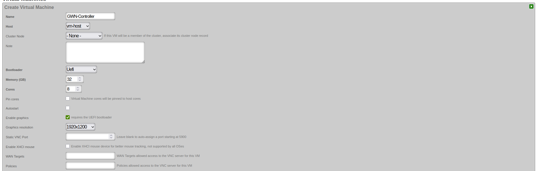
Begin by accessing the Virtualization Management interface and navigate to the Virtual Machines section. Click "Create Virtual Machine" to open the VM creation wizard.
Basic Configuration Parameters:
Virtual Machine Identification: - Name: Enter a descriptive name for your VM (e.g., "Ubuntu-Server-01") - Host: Select the physical host system where the VM will run - Cluster Node: Select "- None -" if the VM won't be part of a cluster
Resource Allocation: - Memory (GB): Allocate appropriate RAM based on your workload requirements - Ubuntu Server minimum: 2GB - Recommended for applications: 8GB+ - Enterprise applications: 32GB+ for optimal performance - Cores: Assign CPU cores based on expected workload - Basic server: 2-4 cores - Application server: 4-8 cores - Database or enterprise applications: 8+ cores - Pin cores: Leave unchecked for general use
Boot Configuration: - Bootloader: Select "Uefi" for modern operating systems - Autostart: Check if VM should start automatically when host boots
Graphics and Remote Access:
- Enable graphics: Required for graphical VNC console access via the scaffold. This option may only be enabled for VMs using the UEFI bootloader. Note that CLI console access is always available via vm console <vmname> from the rXg CLI regardless of this setting.
- Graphics resolution: Select appropriate resolution (e.g., 1920x1200)
- Static VNC Port: Leave blank for auto-assignment
- Enable XHCI mouse: Leave unchecked unless needed
Step 2: Configure Network and Storage
After setting basic parameters, configure the network interfaces and virtual disks for your VM.
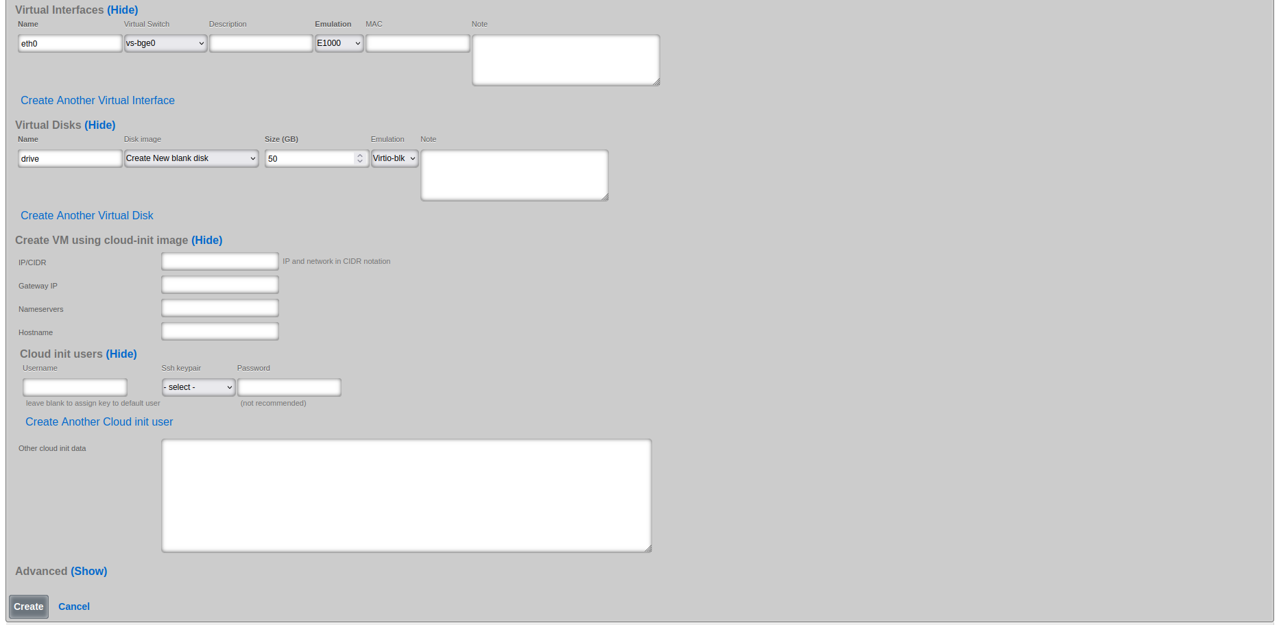
Virtual Network Interface Configuration:
Primary Interface (eth0): - Name: eth0 (default primary interface name) - Virtual Switch: Select appropriate virtual switch (e.g., vs-bge0) - Emulation: E1000 (broad compatibility) or Virtio-net (better performance) - MAC Address: Auto-generated or specify custom if required
Virtual Disk Configuration:
Primary Disk: - Name: drive (default primary disk identifier) - Disk Image: Select "Create New blank disk" - Size (GB): Allocate appropriate storage - Ubuntu Server minimum: 10GB - Recommended for applications: 25-50GB - Enterprise deployments: 50GB+ - Emulation: Virtio-blk (recommended for Linux guests)
Cloud-init Configuration (Optional):
Cloud-init configuration is used for automated initial setup of cloud-init enabled images (such as Ubuntu Cloud Images). Note: Cloud-init requires a pre-built cloud-init enabled disk image, not an ISO installation. When using cloud-init, select the cloud image in the Virtual Disk configuration instead of creating a new blank disk. The VM will boot from this image and automatically apply the cloud-init configuration.
Cloud-init options: - IP/CIDR: Static IP configuration (e.g., 192.168.1.100/24) - Gateway IP: Default gateway for the network - Nameservers: DNS servers (comma-separated) - Hostname: System hostname - Username: Default user account - SSH keypair: SSH public key for passwordless access
Step 3: Select Installation Media
Once VM configuration is complete, you'll see it listed in the Virtual Machines table. Select the installation ISO and begin the installation process.
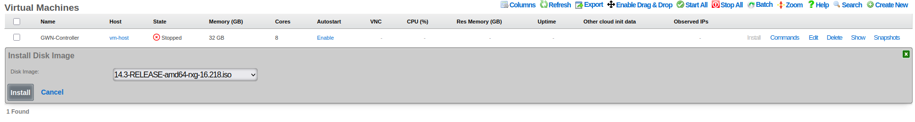
Installation Media Selection: 1. Locate your VM in the Virtual Machines list 2. Click the "Install" action link on the VM row to access installation media selection 3. Select installation ISO from the dropdown - Choose "ubuntu-22.04.5-live-server-amd64.iso" or similar Ubuntu Server ISO - Ensure the ISO matches your intended OS version and architecture 4. Confirm to mount the ISO and prepare for installation
Important: If you have graphics enabled on the VM, you must connect to the console using VNC or the scaffold console link before the VM will begin the installation process.
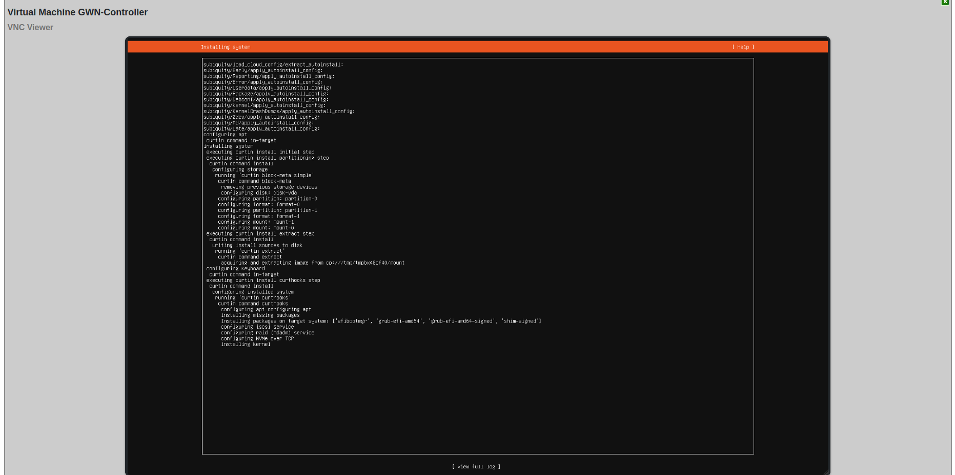
Step 4: Monitor Installation Status
After mounting the installation ISO, verify that the VM is ready for OS installation.

Installation Status Verification: - Status Message: "Install initiated" confirms ISO was successfully mounted - VM State: Shows as "Stopped" (expected before starting installation) - Next Steps: Click on VM name to access detailed controls and start the VM
Step 5: Access VNC Console
Use the VNC console to interact with the VM during installation and initial configuration.
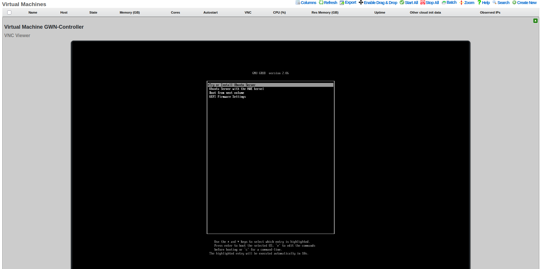
VNC Console Access: 1. Click on the VM name to access the detailed management page 2. VNC Viewer section provides browser-based console access 3. Boot process shows GRUB bootloader with Ubuntu installation options: - "Try or Install Ubuntu Server" (standard installation) - "Ubuntu Server with the HWE kernel" (Hardware Enablement kernel) - "Boot from next volume" (skip to next boot device) - "UEFI Firmware Settings" (access UEFI configuration)
Installation Process: Navigate through the Ubuntu Server installation wizard using: - Arrow keys ( ) to navigate menu options - Tab to move between form fields - Enter to select/confirm options - Space to toggle checkboxes - Esc to go back or cancel
Installation Wizard Steps: 1. Language selection: Choose installation language 2. Keyboard configuration: Select keyboard layout 3. Network configuration: Usually auto-configured via DHCP 4. Disk partitioning: Select "Use entire disk" for VMs 5. User account creation: Set username, password, and server name 6. Package selection: Enable OpenSSH server (recommended)
Step 6: Post-Installation Configuration
After installation completes and the system reboots, the console shows the login prompt with network configuration information.
First Boot Information: The system displays: - Network interface configuration with assigned IP addresses - Available management tools and commands - System services status - Installation completion status
Initial System Configuration:
1. Note the IP address displayed at login prompt
2. SSH into the system using credentials created during installation:
bash
   ssh username@ip-address
3. Update the system immediately after first login:
bash
   sudo apt update
   sudo apt upgrade -y
   sudo reboot
4. Configure additional settings as needed:
- Set static IP if required
- Configure firewall rules
- Set hostname if not done during installation
Virtualization Hosts
The Virtualization Hosts scaffold enables creation, modification, and deletion of a host. The first step to creating a virtual machine in rXg is creating a virtualization host.
The Name field is an arbitrary string used to identify the host. This string is used for identification purposes only.
A virtualization host can be created on any of the bare metal machines in a cluster. The Node dropdown allows you to select the intended target for this configuration.
The Autostart Delay field defines the number of seconds to wait between starting each virtual machine with autostart enabled.
The Virtual Switches field allows for the creation of vswitches that virtual ports can later be attached to. One virtual switch per host interface will automatically be created when you create a new host.
The Virtual Machines field displays all virtual machines that are either unassigned (unchecked) or assigned (checked) to this host.
The Disk Images link, when selected, will allow the operator to manage the .iso files stored for virtual machine creation. Create New will provide the operator with options to either upload or download a new .iso file. The Filename field is required and will be used to reference the associated .iso file. The rXg can directly download a .iso file from a remote destination specified in the URL field. Alternatively, you can select Choose File and select a .iso file from your local machine for upload.
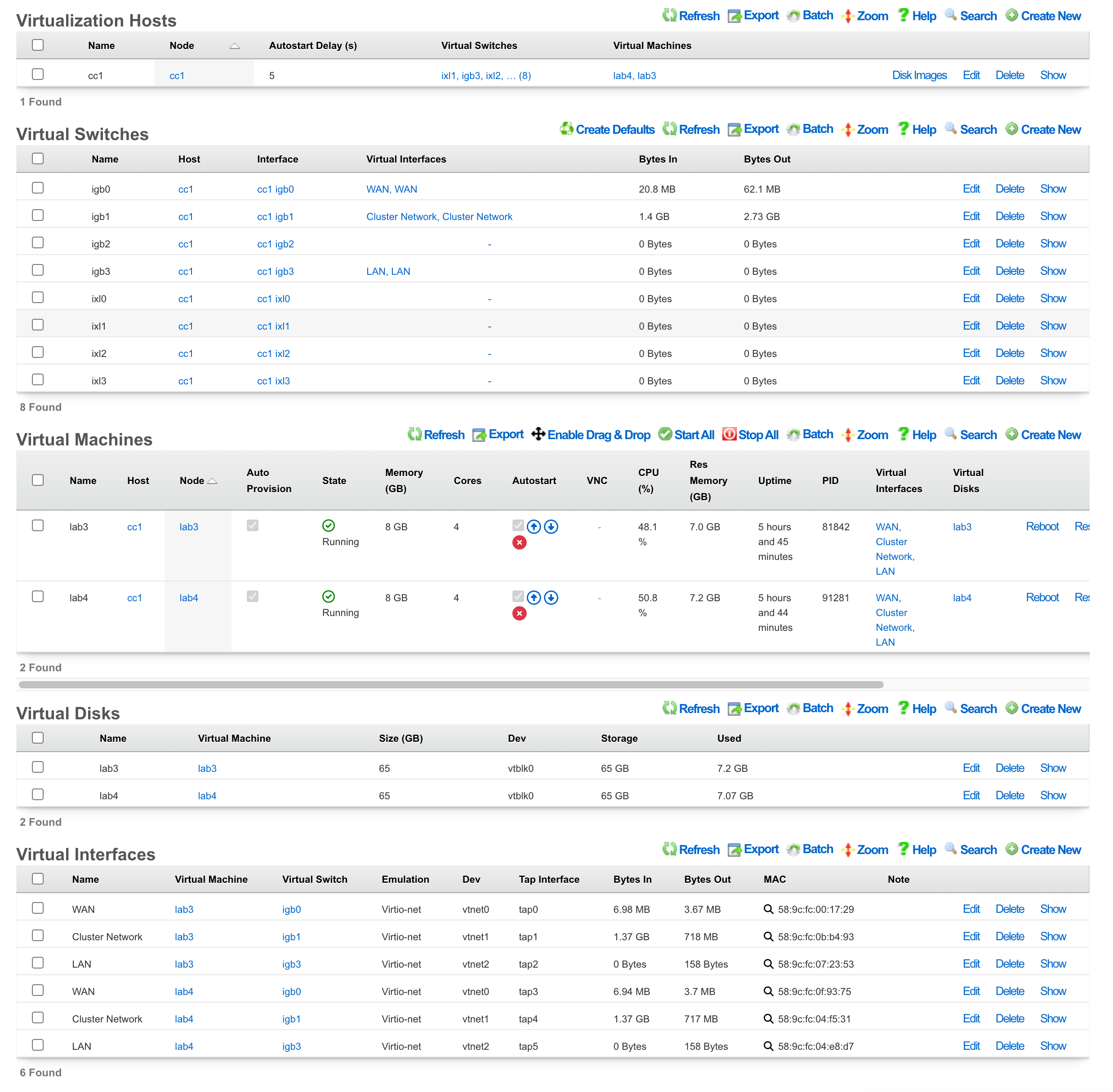
Virtual Machines
The Virtual Machines scaffold enables creation, modification, and deletion of virtual machines.
The Name field is an arbitrary string used to identify the host. This string is used for identification purposes only.
The Host dropdown allows you to specify the host for the virtual machine creation.
If this VM is to be part of a cluster, and the Virtualization Host is the CC, you can use the Cluster Node dropdown to automate the clustering configuration. The rXg will combine the data collected from this form with available information from the CC, create a configuration template, and automatically apply it after the software installation is complete. This process allows the VM to join the cluster automatically. The cluster node dropdown will allow you to select an existing cluster node record or create a new one. If you choose an existing record, you need to check the Auto Provision option to activate this feature. All other required information is collected from the current configuration. If you choose Create New , providing the Node Mode and Node IP address will also be necessary.
The Bootloader field allows for selecting a specific set of booting instructions that is most appropriate for your virtual machine. Use Bhyveload for rXg.
The Memory field allows the number of gigabytes of memory that should be allocated from the host to the virtual machine to be specified.
The Cores field allows the number of CPU cores that should be allocated from the host to the virtual machine to be specified.
The Autostart checkbox, if checked, will automatically start the virtual machine when the host starts. A delay between virtual machine starts can be configured in the host scaffold.
The Enable Graphics field, if selected, will start a VNC server to provide GUI access to the VM.
The Virtual interfaces section allows for the creation of virtual interfaces that can connect the virtual machine to the virtual switch. Creating a virtual interface in this scaffold will also add it to the Virtual Interfaces scaffold. The name field is an arbitrary string used to identify the interface. This string is used for identification purposes only. The emulation field allows for the specification of the emulation type. Virtio-net is recommended in most cases. The virtual switch dropdown allows you to select with which switch the interface you are creating will be assigned. A virtual switch enables VM interfaces to communicate with each other; VMs can reach external networks via Layer 3 routing through the host, or via direct Layer 2 bridging if the switch has a physical interface assigned. The MAC field allows the assignment of a custom MAC address to the interface. Leaving this field blank will result in a MAC address being automatically created.
The Virtual disks section allows for creating a virtual drive that can connect to this virtual machine. Creating a virtual disk in this scaffold will also add it to the Virtual Disks scaffold. The name field is an arbitrary string used to identify the interface. This string is used for identification purposes only. The Size field specifies the number of gigabytes of drive space that should be allocated from the host to the virtual machine. The emulation field allows for the specification of the emulation type. Virtio-blk is recommended in most cases.
Virtual Switches
The Virtual Switches scaffold enables the creation, modification, and deletion of virtual switches.
The Name field is an arbitrary string used to identify the host. This string is used for identification purposes only.
The Host dropdown allows you to specify the host for the virtual switch creation.
The Switch Type dropdown allows a switch type to be specified. Standard is recommended for most cases.
The Interface dropdown provides a list of available physical interfaces from the host machine. Selecting a physical interface is optional - virtual switches function fully without a physical interface assigned. When a physical interface is selected, VMs on the switch gain direct Layer 2 access to that physical network segment. When no physical interface is assigned, VMs can still communicate with each other on the switch and reach external networks via Layer 3 routing through the host. Each physical interface can only be assigned to one virtual switch.
The Virtual Interfaces field provides a list of available virtual interfaces that can be assigned to this switch. Selecting an interface from this dropdown will assign it to this virtual switch and unassign it from any other switch.
Virtual Disks
The Virtual Disks scaffold enables the creation, modification, and deletion of virtual disks.
The Name field is an arbitrary string used to identify the host. This string is used for identification purposes only.
The Virtual Machine dropdown specifies with which virtual machine this disk should be associated.
The Size (GB) field specifies the number of gigabytes of drive space that should be allocated from the host to the virtual machine.
The emulation field allows for the specification of the emulation type. Virtio-blk is recommended in most cases.
Virtual Interfaces
The Virtual Interfaces scaffold enables the creation, modification, and deletion of virtual interfaces.
The Name field is an arbitrary string used to identify the host. This string is used for identification purposes only.
The Virtual Machine dropdown allows you to select with which virtual machine the interface you are creating will be assigned.
The Virtual Switch dropdown allows you to select with which switch the interface you are creating will be assigned. A virtual switch enables VM interfaces to communicate with each other. VMs can reach external networks via Layer 3 routing through the host, or via direct Layer 2 bridging if the switch has a physical interface assigned.
The Emulation field allows for the specification of the emulation type. Virtio-net is recommended in most cases.
The MAC field allows the assignment of a custom MAC address to the interface. Leaving this field blank will result in a MAC address being automatically created.
Virtual Snapshots
The Virtual Snapshots scaffold represents one of the most powerful features of the rXg virtualization platform, providing comprehensive snapshot management capabilities that leverage the advanced features of ZFS technology for reliable backup and recovery operations. This sophisticated system enables administrators to create point-in-time captures of virtual machine states, providing an essential foundation for data protection, disaster recovery, and system maintenance workflows.
The snapshot creation process captures the complete state of a virtual machine at a specific moment in time, including all virtual disk data, system configuration settings, and the current operational state of the VM. This comprehensive capture is made possible through ZFS copy-on-write technology, which provides extremely efficient storage utilization by only storing the differences between the original data and any subsequent changes. This approach means that creating a snapshot is nearly instantaneous regardless of the size of the virtual machine, and the initial storage overhead is minimal.
Rollback operations provide administrators with the ability to restore virtual machines to previous snapshot states, enabling quick recovery from system issues, failed updates, or configuration problems. However, it is crucial to understand that rollback operations automatically delete all snapshots that were created after the selected restore point. This behavior ensures data consistency but requires careful planning when implementing rollback procedures, as any changes made after the snapshot was taken will be permanently lost.
The backup and export functionality allows snapshots to be downloaded as standalone backup files, facilitating external storage for long-term archival, disaster recovery planning, or virtual machine migration between different rXg systems. These exported snapshots maintain complete fidelity to the original VM state and can be imported into other compatible systems, making them invaluable for creating development environments, testing scenarios, or implementing comprehensive disaster recovery strategies.
Storage efficiency remains a key advantage of the ZFS-based snapshot system, as snapshots only consume additional storage space for data blocks that have changed since the snapshot was created. This characteristic makes regular snapshot creation practical even for large virtual machine deployments, as the storage overhead grows incrementally with the amount of data modification rather than requiring full copies of the virtual machine disk images. Nonetheless, attention should be paid to the number of snapshots and their size over time, since snapshots will continue to grow as data changes on the virtual machine's disk, and can potentially consume a large portion of the host's disks if left to grow unchecked.
Virtual Host Replication Groups
Virtual Host Replication Groups enable VM replication across multiple virtualization hosts for high availability, disaster recovery, and automated backup scheduling. This feature ensures that VMs can be recovered on alternate hosts in case of hardware failure, providing enterprise-grade data protection capabilities.
How Replication Works
The rXg uses ZFS replication to efficiently transfer VM data between hosts in a replication group:
- Initial backup: Creates a full ZFS snapshot of each VM's storage datasets
- Incremental backups: Subsequent backups transfer only changed blocks since the previous backup, dramatically reducing transfer time and bandwidth requirements
- Compression: Backup data is compressed during transfer to minimize network bandwidth consumption
- Online operation: VMs can continue running during backup operations with minimal performance impact
Replication Group Requirements
To configure a functional replication group:
- Minimum hosts: A replication group requires at least two virtualization hosts to ensure there is always an alternate destination for VM recovery
- Matching switch configuration: All virtualization hosts in a replication group must have the same number of virtual switches, ensuring VMs can maintain network connectivity when restored to a different host
- Storage capacity: Destination hosts must have sufficient storage capacity to accommodate replicated VM data
Backup Scheduling
Configure automated backup schedules based on your recovery point objective (RPO):
- Daily backups: Suitable for most workloads with moderate data change rates
- Weekly backups: Appropriate for static systems or development environments
- Monthly backups: For archival purposes or systems with minimal changes
- Manual backups: Use the "Create Backup Now" action before major changes or maintenance operations
Schedule backups during periods of low VM activity to minimize performance impact and reduce backup duration.
Failover and Recovery
In case of host failure, VMs can be restored on any other host in the replication group:
- Data availability: VM data is already present on the destination host from replication
- Network mapping: Virtual Switch Replication Groups ensure correct network configuration by mapping source virtual switches to destination virtual switches
- Recovery time: Depends on the age of the most recent backup; more frequent backups provide lower recovery time objectives (RTO)
Best Practices
- Monitor backup status: Regularly check the "Last Backup At" timestamp to ensure backups are completing successfully
- Test recovery procedures: Periodically test VM recovery to ensure backups are valid and the recovery process is well understood
- Off-peak scheduling: Schedule backups during low-usage periods to minimize impact on production workloads
- Storage monitoring: Monitor ZFS storage utilization on destination hosts to ensure adequate capacity for ongoing replication
Advanced VM Features
The rXg virtualization platform extends far beyond basic virtual machine creation and management, incorporating sophisticated features that address enterprise-level requirements for automation, performance optimization, and operational efficiency. These advanced capabilities transform the platform from a simple virtualization solution into a comprehensive infrastructure management system that can handle complex deployment scenarios and demanding performance requirements.
IP Address Assignment and Cloud-Init Integration
The network configuration capabilities of rXg virtual machines represent a significant advancement in deployment automation and operational consistency. The system supports both static IP configuration and dynamic DHCP assignment, with each method offering distinct advantages for different use cases and deployment scenarios.
Static IP configuration enables administrators to assign fixed IP addresses using industry-standard CIDR notation, such as "192.168.1.100/24", providing predictable network addressing that is essential for server deployments, service hosting, and infrastructure components that require consistent network accessibility. This configuration method extends beyond simple IP assignment to include comprehensive network parameter specification, including default gateway configuration for external network routing and DNS server assignment for domain name resolution. The system automatically generates cloud-init configuration files that ensure these network settings are properly applied during the virtual machine boot process, eliminating the need for manual network configuration within the guest operating system.
DHCP support provides flexibility for dynamic network environments and temporary deployments where fixed IP addresses are not required or practical. Administrators can simply leave the IP configuration fields blank, and the virtual machine will automatically obtain network configuration from DHCP services provided by the virtual switch infrastructure or external DHCP servers. This approach is particularly valuable for development environments, temporary testing scenarios, and workstation-style deployments where network mobility and simplified configuration management are prioritized.
The cloud-init automation system represents a fundamental shift in virtual machine deployment methodology, providing comprehensive initialization capabilities that extend far beyond network configuration. This sophisticated system automatically handles network configuration based on the specified IP settings, creates user accounts with appropriate permissions and access controls, deploys SSH public keys for secure remote access, configures hostname and system identification parameters, and executes custom initialization scripts and configuration procedures. The integration of cloud-init technology ensures that virtual machines are fully configured and ready for use immediately upon first boot, dramatically reducing deployment time and eliminating configuration inconsistencies that can arise from manual setup procedures.
Manual Cloud-Init Configuration Examples
For advanced deployment scenarios that require precise control over virtual machine initialization, administrators can utilize the "Other Cloud Init Data" field within the virtual machine configuration interface to specify custom cloud-init YAML configuration. This capability enables sophisticated deployment automation that extends beyond the standard IP assignment fields to include complex network topologies, custom software installation, user management, and automated system configuration procedures.
A basic static IP configuration example demonstrates the fundamental approach to manual cloud-init network specification. To configure a virtual machine with a static IP address of 192.168.1.100 with a 24-bit subnet mask, default gateway at 192.168.1.1, and DNS servers at 8.8.8.8 and 8.8.4.4, administrators would include the following YAML configuration in the "Other Cloud Init Data" field:
# Network configuration for static IP assignment
network:
  version: 2
  ethernets:
    eth0:
      addresses:
        - 192.168.1.100/24
      gateway4: 192.168.1.1
      nameservers:
        addresses:
          - 8.8.8.8
          - 8.8.4.4
        search:
          - example.com
          - localdomain

# System configuration
hostname: web-server-01
fqdn: web-server-01.example.com
timezone: America/New_York

# Package installation
packages:
  - htop
  - curl
  - vim
  - nginx

# User management
users:
  - name: admin
    groups: [sudo, www-data]
    shell: /bin/bash
    ssh_authorized_keys:
      - ssh-rsa AAAAB3NzaC1yc2EAAAA... [email protected]

# Custom commands executed after boot
runcmd:
  - systemctl enable nginx
  - systemctl start nginx
  - ufw allow 'Nginx Full'
  - echo "Web server configured" >> /var/log/cloud-init-setup.log
For more complex deployments involving multiple network interfaces, administrators can specify detailed configurations for each interface with different IP addressing schemes, routing tables, and network purposes. A multi-interface configuration example might include a management interface on the 192.168.1.0/24 network, an application interface on the 10.0.1.0/24 private network, and a storage interface on the 172.16.1.0/24 network with jumbo frame support:
# Multi-interface network configuration
network:
  version: 2
  ethernets:
    eth0:
      # Management interface
      addresses:
        - 192.168.1.100/24
      gateway4: 192.168.1.1
      nameservers:
        addresses: [192.168.1.10, 8.8.8.8]
      routes:
        - to: 0.0.0.0/0
          via: 192.168.1.1
          metric: 100
    eth1:
      # Application interface
      addresses:
        - 10.0.1.50/24
      routes:
        - to: 10.0.0.0/8
          via: 10.0.1.1
          metric: 200
    eth2:
      # Storage interface with jumbo frames
      addresses:
        - 172.16.1.10/24
      mtu: 9000

# Complete system configuration
hostname: database-server
fqdn: database-server.company.local
timezone: America/New_York

# Comprehensive package installation
packages:
  - postgresql-13
  - postgresql-contrib
  - fail2ban
  - ufw
  - htop
  - iotop

# Advanced user configuration
users:
  - name: dbadmin
    groups: [sudo, postgres]
    shell: /bin/bash
    ssh_authorized_keys:
      - ssh-rsa AAAAB3NzaC1yc2EAAAA... [email protected]
    sudo: ['ALL=(ALL) NOPASSWD:ALL']

# File system configuration
mounts:
  - ["/dev/vdb", "/var/lib/postgresql", "ext4", "defaults", "0", "2"]

# Custom file creation
write_files:
  - path: /etc/postgresql/13/main/postgresql.conf
    content: |
      listen_addresses = '192.168.1.100'
      port = 5432
      max_connections = 100
      shared_buffers = 256MB
    permissions: '0644'
    owner: postgres:postgres

# Post-installation commands
runcmd:
  - systemctl enable postgresql
  - systemctl start postgresql
  - ufw default deny incoming
  - ufw allow ssh
  - ufw allow 5432/tcp
  - ufw --force enable
  - sudo -u postgres createdb company_db
  - echo "Database server setup completed" >> /var/log/cloud-init-setup.log
The cloud-init configuration system supports extensive customization options including VLAN configuration for network segmentation, custom routing tables for complex network topologies, file system mounting for additional storage devices, and comprehensive security configuration including firewall rules and access controls. The YAML format requires precise indentation and syntax adherence, making it essential to validate configurations in development environments before applying them to production virtual machines.
Performance and Resource Management
The performance optimization features built into the rXg virtualization platform address the critical need for consistent, predictable performance in enterprise virtual machine deployments. These capabilities enable administrators to fine-tune resource allocation and ensure that critical workloads receive appropriate system resources while maintaining overall system stability and efficiency.
CPU core pinning functionality allows administrators to dedicate specific physical CPU cores exclusively to individual virtual machines, providing improved performance isolation and ensuring consistent CPU performance characteristics. This feature is particularly valuable for latency-sensitive applications, real-time processing workloads, and high-performance computing scenarios where CPU scheduling predictability is essential. By preventing the hypervisor from migrating virtual machine threads across different CPU cores, core pinning eliminates cache pollution effects and reduces context switching overhead, resulting in more consistent performance characteristics and reduced performance variability.
Memory wiring capabilities prevent virtual machine memory from being swapped to disk storage, ensuring consistent memory performance and eliminating the performance penalties associated with swap operations. This feature is crucial for applications with strict latency requirements, database workloads, and memory-intensive applications where swap-induced delays would significantly impact performance. Memory wiring requires careful planning to ensure that sufficient physical RAM is available on the host system, but provides substantial performance benefits for critical workloads that justify the resource reservation.
Graphics support extends the virtualization platform's capabilities to include desktop virtualization scenarios and applications that require graphical user interfaces. The integrated VNC server provides remote access to virtual machine desktops with configurable resolution settings ranging from standard definitions up to high-definition formats. Static VNC port assignment ensures consistent remote access capabilities, while XHCI mouse support provides improved mouse performance and responsiveness in graphical environments. These features are particularly valuable for Windows virtual machines, desktop virtualization deployments, and applications that require interactive graphical interfaces.
Priority control mechanisms enable administrators to establish resource allocation hierarchies that ensure critical virtual machines receive preferential treatment during periods of resource contention. By setting appropriate priority levels, administrators can guarantee that essential services maintain adequate performance even when the host system experiences high resource utilization. This capability is essential for mixed workload environments where different virtual machines have varying criticality levels and performance requirements.
Storage and Template Management
The storage subsystem of the rXg virtualization platform leverages the advanced capabilities of ZFS to provide a robust, efficient, and feature-rich foundation for virtual machine storage requirements. This integration goes beyond simple disk provisioning to include comprehensive data protection, performance optimization, and management capabilities that address enterprise storage needs.
ZFS integration provides automatic dataset creation with optimized configuration parameters specifically tuned for virtual machine workloads. The system automatically configures ZFS datasets with a 64K record size that aligns with typical virtual machine I/O patterns, providing improved performance for database workloads, file systems, and general-purpose virtual machine operations. The copy-on-write functionality inherent in ZFS provides data integrity guarantees while enabling efficient snapshot operations that consume minimal additional storage space.
Template support revolutionizes virtual machine deployment by enabling rapid provisioning from pre-configured disk images and cloud-ready templates. The system supports automatic conversion and application of various image formats, including qcow2, raw disk images, and cloud-optimized images from popular Linux distributions. This capability dramatically reduces deployment time by eliminating the need for manual operating system installation and basic configuration, enabling administrators to deploy fully configured virtual machines in minutes rather than hours.
Disk image management capabilities provide comprehensive support for multiple image formats with integrated upload and download functionality for both ISO installation media and cloud-ready disk images. The system handles format conversion automatically, ensuring compatibility across different image types while maintaining data integrity throughout the import and export process. This flexibility enables administrators to leverage existing image libraries, create standardized deployment templates, and maintain consistent virtual machine configurations across different environments.
Network Configuration and Security
The networking capabilities of the rXg virtualization platform represent a sophisticated approach to virtual network management that addresses both performance requirements and security considerations essential for enterprise deployments. This comprehensive networking framework provides administrators with the tools necessary to create complex network topologies, implement security boundaries, and optimize network performance for diverse workload requirements.
Advanced Networking Architecture
The virtual switch infrastructure forms the foundation of the rXg networking architecture, providing Layer 2 connectivity services that enable virtual machines to communicate with each other and with external networks. These virtual switches incorporate advanced features that extend beyond basic network connectivity to include comprehensive management, monitoring, and optimization capabilities.
Understanding Virtual Switch Network Modes
Virtual switches in the rXg virtualization platform operate using FreeBSD bridge interfaces, which provide flexible networking capabilities through two distinct operational modes. Understanding these modes is essential for designing effective network topologies and implementing appropriate connectivity patterns for different deployment scenarios.
Direct Bridge Mode (Layer 2 Bridging)
When a virtual switch is connected to a physical network interface, it operates in direct bridge mode, creating a Layer 2 network segment that spans both virtual and physical networks. In this configuration, virtual machines connected to the switch share the same broadcast domain as devices on the physical network, enabling direct communication without routing overhead.
Key characteristics of direct bridge mode: - Virtual machine traffic is directly bridged to the physical network - VMs appear as peers on the physical network segment - No IP address assignment required on the bridge interface itself - Minimal latency and maximum throughput - VMs can obtain DHCP addresses from physical network DHCP servers - Suitable for scenarios requiring direct Layer 2 connectivity
This mode is ideal for deployments where virtual machines need to integrate seamlessly with existing physical network infrastructure, such as when migrating physical servers to virtual machines while maintaining existing network addresses and connectivity patterns.
Routed Mode (Layer 3 Routing)
When a virtual switch operates without a physical interface connection, it creates an isolated Layer 2 segment where virtual machines can communicate with each other at the data link layer. However, the underlying FreeBSD bridge interface can be assigned an IP address, enabling the rXg host to route traffic between the virtual switch network and other networks (both physical interfaces and other virtual switches) at Layer 3.
Key characteristics of routed mode: - Virtual machines form an isolated Layer 2 segment - The bridge interface acts as the default gateway for VMs on the switch - Traffic between virtual switches and physical networks is routed by the rXg host - Enables network segmentation and security boundary implementation - Supports complex multi-tier network architectures - Allows firewall rules and traffic shaping between network segments
This mode provides maximum flexibility for creating sophisticated network topologies with controlled traffic flow between different security zones, application tiers, and functional network segments.
Network Traffic Flow Architecture
The following diagram illustrates how network traffic flows through the virtualization infrastructure in both bridge and routed modes:
                         DIRECT BRIDGE MODE


     VM 1    192.168.1.100


        tap0 (no IP)


   bridge0/vm-lan  (no IP configured)
    Layer 2 only


            Physical Interface Member


    em0 Physical   Connected to external switch
     Interface


    External Network (192.168.1.0/24)

    VM traffic is directly bridged - no routing involved


                           ROUTED MODE


     VM 1                VM 2


        10.10.1.10           10.10.1.11
        tap0                 tap1


      bridge0/vm-internal
      IP: 10.10.1.1/24                 Bridge has IP address!
      (VM default gateway)


                  No physical interface - isolated L2 segment


     rXg Host Routing Stack            Layer 3 routing happens here
     (gateway_enable="YES")
     Routes between interfaces


                  Routing decisions based on destination


     em0             bridge1      (Another virtual switch)
   Physical          10.20.1.1


                           Other VMs (10.20.1.0/24)


  External Network

  VM traffic is routed through the rXg host's routing stack


                      HYBRID MODE (COMBINED)

  Production VMs (Direct Bridge)         Internal VMs (Routed)

   Web VM    192.168.1.50                 App VM   10.10.1.10


   bridge-dmz  (no IP)                  bridge-app   10.10.1.1
    + em0                               (isolated)


                                        rXg Routing
                                        + Firewall


                   External Network

  DMZ VMs have direct L2 access - App VMs routed with firewall control
Configuration Requirements for Routed Mode
To enable Layer 3 routing between virtual switches and physical interfaces, the rXg host must have IP forwarding enabled. This is controlled by the FreeBSD gateway_enable parameter, which sets the net.inet.ip.forwarding sysctl value to 1. The rXg automatically configures this parameter appropriately for virtualization deployments.
When implementing routed mode networking: 1. Assign an IP address to the bridge interface (becomes the VM gateway) 2. Configure VMs with IP addresses in the bridge's subnet 3. Set the bridge IP as the VM default gateway 4. Implement appropriate firewall rules to control inter-network traffic 5. Configure routing policies for traffic between virtual and physical networks
Network Topology Design Patterns
The flexibility of the virtual switch architecture enables several common network topology patterns:
- Single Bridge with Physical Uplink: All VMs share one network segment with direct external access
- Multiple Isolated Bridges with Routing: Different VM groups on separate networks with controlled routing
- DMZ + Internal Architecture: Public-facing VMs on bridged network, application VMs on routed internal network
- Three-Tier Architecture: Separate networks for presentation, application, and data tiers with routing policies
- Management Network Separation: Dedicated isolated network for administrative access with restricted routing
CIDR configuration capabilities enable administrators to define and manage IP address spaces at the virtual switch level, providing automatic subnet management and IP validation services that ensure network configuration consistency. When a virtual switch is configured with a specific CIDR range, the system automatically validates virtual machine IP assignments against this range, preventing configuration errors and network conflicts that could disrupt service availability. This validation extends to gateway configuration verification, ensuring that default gateways are properly positioned within the defined subnet boundaries and are accessible from assigned virtual machine IP addresses.
Private network functionality provides the capability to create completely isolated network segments that operate independently of external network infrastructure. These private networks enable virtual machines to communicate with each other using standard networking protocols while remaining completely isolated from external network access. This isolation is particularly valuable for creating secure development environments, implementing network segmentation for compliance requirements, and establishing protected communication channels for sensitive applications that require network isolation.
MTU configuration support enables administrators to optimize network performance by adjusting the Maximum Transmission Unit size to match specific application requirements and network infrastructure capabilities. Standard Ethernet networks typically operate with 1500-byte MTU values, but the system supports configuration of jumbo frames up to 9000 bytes for high-throughput applications that can benefit from reduced packet processing overhead. The system also supports MTU reduction for networks that require additional protocol overhead or tunneling encapsulation that would otherwise cause packet fragmentation.
Traffic monitoring and statistics collection provide comprehensive visibility into network utilization patterns and performance characteristics. The system automatically tracks and reports detailed statistics including total bytes transmitted and received, packet counts, error rates, and bandwidth utilization patterns. These metrics are essential for capacity planning, performance troubleshooting, and identifying network bottlenecks that could impact virtual machine performance. The monitoring system integrates with the broader rXg management infrastructure to provide alerts and notifications when network utilization exceeds defined thresholds or when error conditions are detected.
Network segmentation capabilities enable administrators to create sophisticated network topologies that separate different types of traffic based on security requirements, performance characteristics, and functional purposes. DMZ networks can be established for internet-facing services that require external connectivity while maintaining isolation from internal network resources. Internal networks provide secure communication channels for application components that require high-speed, low-latency connectivity without exposure to external threats. Management networks enable administrative access and monitoring traffic to be segregated from production application traffic, improving both security and performance predictability. Storage networks can be dedicated to backup, replication, and storage access traffic, ensuring that these high-bandwidth operations do not interfere with application performance.
MAC address management incorporates both automatic generation capabilities and support for custom address assignment based on specific deployment requirements. The automatic generation system utilizes a reserved vendor prefix of 58:9c:fc that identifies virtual machines created within the rXg environment, followed by algorithmically generated address components that ensure uniqueness within the network domain. This approach provides consistent, predictable MAC address assignment while eliminating conflicts that could arise from random address generation. For deployments that require specific MAC address assignments due to licensing requirements, wake-on-LAN functionality, or integration with external network management systems, the platform supports manual MAC address specification with validation to prevent duplicate assignments.
Security and Isolation Framework
The security architecture of the rXg virtualization networking system incorporates multiple layers of protection and isolation mechanisms designed to address the complex security requirements of modern virtual infrastructure deployments. These security features operate at both the network and system levels to provide comprehensive protection against unauthorized access, data exfiltration, and lateral movement threats.
Network isolation represents the primary security mechanism for controlling communication between virtual machines and external network resources. Private virtual switches create completely isolated network segments that prevent unauthorized network access while enabling legitimate communication between authorized virtual machines. This isolation operates at the network layer, preventing any network traffic from traversing between isolated segments regardless of the network protocols or applications involved. The isolation is enforced by the underlying FreeBSD networking stack and bhyve hypervisor, providing robust protection that cannot be bypassed through software manipulation or configuration changes within the virtual machines themselves.
Resource control mechanisms extend beyond simple network isolation to include comprehensive resource allocation and limitation capabilities that prevent resource exhaustion attacks and ensure fair resource distribution among virtual machines. CPU resource controls enable administrators to establish maximum CPU utilization limits for individual virtual machines, preventing any single virtual machine from consuming excessive CPU resources that could impact the performance of other virtual machines on the same host. Memory allocation controls ensure that virtual machines cannot exceed their allocated memory limits, preventing memory exhaustion conditions that could destabilize the host system or impact other virtual machines. Storage resource controls limit disk I/O rates and storage space consumption, ensuring that virtual machines cannot monopolize storage resources or perform disk-based denial of service attacks against other virtual machines.
Access management capabilities provide multiple layers of authentication and authorization controls that ensure only authorized users and systems can access virtual machine resources and management interfaces. Network-based access controls enable administrators to implement IP address restrictions, MAC address filtering, and protocol-based access limitations that restrict network access based on source identity and connection characteristics. Authentication integration with enterprise directory services ensures that virtual machine access is governed by centralized identity management policies and that access permissions are automatically updated when user roles or responsibilities change. Multi-factor authentication support provides additional security for administrative access to critical virtual machine infrastructure and management interfaces.
Command-Line Tools and Automation Infrastructure
The rXg virtualization platform incorporates a comprehensive suite of command-line tools and automation capabilities designed to streamline virtual machine deployment, management, and operational procedures. These tools enable both interactive administration and fully automated deployment scenarios, supporting everything from single virtual machine creation to large-scale infrastructure provisioning and management operations.
VM Deployment Tool and Interactive Provisioning
The deploy_vm command-line utility represents a sophisticated approach to virtual machine provisioning that combines the flexibility of command-line operation with the convenience of interactive configuration assistance. This tool addresses the common challenge of virtual machine deployment complexity by providing a guided interface that ensures all necessary configuration parameters are properly specified while maintaining the efficiency and automation potential of command-line operations.
The tool accepts comprehensive configuration parameters directly from the command line, enabling fully automated deployment scenarios where all necessary parameters are known in advance. A typical deployment command such as deploy_vm web-server-01 -c 4 -m 8 -g 50 -n production-switch creates a virtual machine named "web-server-01" with 4 CPU cores, 8 gigabytes of memory, 50 gigabytes of storage, and connectivity to the "production-switch" virtual switch. This direct parameter specification approach is ideal for scripted deployments, infrastructure-as-code implementations, and batch provisioning operations where consistent configuration parameters are applied across multiple virtual machines.
Interactive prompting capabilities ensure that missing or incomplete configuration parameters are properly collected during the deployment process, preventing deployment failures due to incomplete specifications. When required parameters are not provided via command-line arguments, the tool enters an interactive mode that guides administrators through the configuration process, providing context-sensitive help and validation to ensure that all specifications are appropriate for the intended deployment scenario. This interactive approach is particularly valuable for one-off deployments, exploratory configurations, and situations where configuration requirements may not be fully defined at the time of initial deployment.
Disk image selection and management functionality enables administrators to choose from available installation media and pre-configured disk images during the deployment process. The tool provides access to the complete library of uploaded ISO files and cloud-ready disk images, enabling administrators to select the most appropriate base image for their specific deployment requirements. The integration with the disk image management system ensures that selected images are properly validated and compatible with the target virtual machine configuration before deployment proceeds.
Network configuration assistance helps administrators navigate the complexities of virtual network setup by providing guidance on virtual switch selection, IP address assignment, and network connectivity requirements. The tool can automatically suggest appropriate network configurations based on existing virtual switch definitions and network topology, while also supporting manual specification of detailed network parameters for complex deployment scenarios that require specific connectivity arrangements.
API Integration and Programmatic Management
The RESTful API infrastructure provides comprehensive programmatic access to all virtualization platform capabilities, enabling integration with external management systems, automation frameworks, and custom applications that require virtual machine management functionality. These APIs adhere to modern REST architectural principles, providing predictable, standards-based interfaces that support both individual operations and bulk management scenarios.
The virtual machine lifecycle management API accessible at /api/virtual_machines provides complete control over virtual machine creation, configuration, operation, and deletion. This API supports all virtual machine management operations including power state control, configuration modification, resource allocation adjustment, and performance monitoring. The API accepts JSON-formatted requests that specify virtual machine parameters and configuration settings, returning detailed response information that includes virtual machine status, resource utilization metrics, and operational state information. This comprehensive API enables external systems to implement sophisticated virtual machine management workflows that can respond to changing operational requirements and automatically adjust virtual machine configurations based on performance metrics or business logic.
Host configuration management through the /api/virtualization_hosts endpoint enables programmatic management of virtualization host settings including resource allocation policies, network configuration, and performance tuning parameters. This API provides the capability to dynamically adjust host-level settings in response to changing workload requirements, implement automated resource rebalancing across multiple hosts, and maintain consistent configuration standards across the virtualization infrastructure. The API supports both individual host management operations and bulk operations that can simultaneously update configuration settings across multiple hosts in a coordinated manner.
Network management capabilities exposed through the /api/virtual_switches API enable dynamic network topology management including virtual switch creation, configuration modification, and traffic policy implementation. This API supports sophisticated network automation scenarios including automatic network segmentation based on virtual machine characteristics, dynamic VLAN assignment, and traffic shaping policy implementation. The integration with the underlying network infrastructure ensures that API-driven network changes are properly coordinated with physical network configuration and that network policies are consistently enforced across the entire virtual infrastructure.
Snapshot management operations provided by the /api/virtual_snapshots endpoint enable programmatic backup and recovery workflows that can be integrated with broader data protection and disaster recovery systems. This API supports automated snapshot creation based on schedules or trigger events, snapshot lifecycle management including automatic cleanup of old snapshots, and coordinated backup operations that can span multiple virtual machines to ensure consistent backup points across related systems.
Backup and Recovery Tools and Operational Procedures
The specialized backup and recovery utilities integrated into the rXg virtualization platform provide enterprise-grade data protection capabilities that address both routine backup requirements and disaster recovery scenarios. These tools leverage the underlying ZFS storage capabilities to provide efficient, reliable backup operations while maintaining the flexibility necessary to support diverse operational requirements and recovery scenarios.
The bhyve_create_backup utility implements comprehensive virtual machine backup functionality that captures complete virtual machine state including all disk data, configuration settings, and metadata necessary for complete restoration. This tool supports both full and incremental backup operations, with incremental backups leveraging ZFS snapshot capabilities to capture only changed data blocks since the previous backup operation. The backup process includes extensive validation procedures that verify backup completeness and integrity, ensuring that backup files are suitable for reliable restoration operations. The tool supports various backup destinations including local storage, network-attached storage systems, and cloud storage services, providing flexibility in backup storage strategy implementation.
Virtual machine restoration capabilities provided by the bhyve_restore_backup utility enable complete recovery of virtual machines from backup files created by the backup system. The restoration process includes extensive validation of backup file integrity and compatibility with the target virtualization environment, ensuring that restoration operations complete successfully and that restored virtual machines operate correctly. The tool supports restoration to the original virtualization host or to alternative hosts within the virtualization infrastructure, enabling both routine recovery operations and disaster recovery scenarios where the original host system may not be available.
Snapshot export functionality implemented in the bhyve_snapshot_download utility provides the capability to extract individual snapshots from the ZFS storage system for external storage, archival, or migration purposes. This tool creates portable snapshot files that maintain complete fidelity to the original snapshot while being independent of the source ZFS storage system. The export process includes compression and integrity verification capabilities that optimize storage efficiency while ensuring that exported snapshots can be reliably imported into other compatible systems. The tool supports both individual snapshot export operations and batch export scenarios where multiple snapshots can be processed simultaneously.
Snapshot import and restoration capabilities provided by the bhyve_snapshot_restore utility enable the integration of externally stored snapshots back into the active virtualization environment. This tool supports restoration from snapshot files created by the export utility as well as compatible snapshot formats from other virtualization platforms, providing migration capabilities that enable virtual machine movement between different virtualization environments. The import process includes extensive compatibility validation and automatic conversion capabilities that ensure imported snapshots are properly integrated into the target virtualization environment and that restored virtual machines operate correctly within the new environment.
Virtualization Design Guide
Note: We recommend that a single machine with a single instance of rXg be limited to 1500 DPL, 8 CPU cores, and 16 GB of RAM.
No HA Required
- Single rXg Host Internal Dataplane Virtualization
HA Required
- 2-way Symmetric rXg Cluster
- 3-way Symmetric rXg Cluster
- 3-way Asymmetric rXg Cluster
- 4-way Asymmetric rXg Cluster
- 8-way Asymmetric rXg Cluster
Single rXg Host Internal Dataplane Virtualization
- Install rXg on bare metal machine
- Configure bare metal rXg as CC
- Also use the bare metal rXg as virtualization host
- Install (6) vDPs
- Configure bare metal rXg as CC
Example:
- Server with AMD 64-core CPU / 256 GB of RAM
- 6-way IDV (8 cores / 16 GB each)
- 16 cores and 64GB RAM for CC
- 6000 DPL in full operation

2-way Symmetric rXg Cluster
- Install rXg on both bare metal machines.
- Configure bare metal rXgs as symmetric rXg cluster with (2) CCs
- Also use the bare metal rXgs as virtualization hosts
- Install (2) vDPs per node
- Use cluster teaming to facilitate deterministic failover
- Configure bare metal rXgs as symmetric rXg cluster with (2) CCs
Example:
- 2 x servers with AMD 24-core CPU / 64 GB of RAM
- 2-way IDV (8 cores / 16 GB each) on each server
- 8 cores and 32GB RAM for CC
- 4000 DPL in full operation (2000 DPL if one fails)

3-way Symmetric rXg Cluster
- Install rXg on all 3 bare metal machines.
- Configure bare metal rXgs as symmetric rXg cluster with (3) CCs
- Also use the bare metal rXgs as virtualization hosts
- Install (4) vDPs per node
- Use cluster teaming to facilitate deterministic failover
- Configure bare metal rXgs as symmetric rXg cluster with (3) CCs
Example:
- 3 x servers with AMD 48-core CPU / 128 GB of RAM
- 4-way IDV on each server
- 16 cores and 64 GB RAM for CC
- 12000 DPL in full operation (8000 DPL if one fails)

3-way Asymmetric rXg Cluster
- Install rXg on all 3 bare metal machines.
- Configure bare metal rXgs as asymmetric rXg cluster with (1) CC and (2) DPs
- Use the bare metal DP nodes as virtualization hosts
- Install (4) vDPs per DP node
- Configure bare metal rXgs as asymmetric rXg cluster with (1) CC and (2) DPs
Example:
- 3 x servers with AMD 32-core CPU / 64 GB of RAM
- rXg CC runs on bare metal
- 4-way IDV on bare metal rXg DPs
- 16 cores and 40 GB RAM for CC
- 16 cores and 24 GB RAM for VMs - 8000 DPL in full operation (4000 DPL if one fails)

6-way Asymmetric rXg Cluster
- Install rXg on all 4 bare metal machines.
- Configure bare metal rXgs as asymmetric rXg cluster with (2) CCs and (2) DPs
- Use the bare metal DP nodes as virtualization hosts
- Install (4) vDPs per DP node
- Use cluster teaming to facilitate deterministic failover
- Configure bare metal rXgs as asymmetric rXg cluster with (2) CCs and (2) DPs
Example:
- 6 x servers with AMD 32-core CPU / 64 GB of RAM
- 4-way IDV (8 cores / 16 GB each) on each vDP
- Full capacity of bare metal for master and standby CC
- 16000 DPL in full operation (12000 DPL if one CP or DP or both fails)


8-way Asymmetric rXg Cluster
- Install rXg on all 8 bare metal machines.
- Configure bare metal rXgs as asymmetric rXg cluster with (2) CCs and (6) DPs
- Use the bare metal DP nodes as virtualization hosts
- Install (16) vDPs per DP node
- Use cluster teaming to facilitate deterministic failover
- Configure bare metal rXgs as asymmetric rXg cluster with (2) CCs and (6) DPs
Example:
- 8 x servers with 2x AMD 64-core CPU / 512 GB of RAM
- 16-way IDV (8 cores / 16 GB each) on each vDP
- Full capacity of bare metal for master and standby CC
- 96,000 DPL in full operation with room to grow!


