Cluster
The rXg clustering solution simplifies and unifies the management of large scale rXg deployments.

An rXg cluster controller centralizes the configuration, instrumentation, and all operationally relevant persistent storage of a cluster of rXg devices. Synchronized, parallel, highly available, and cost-effective operation of an rXg cluster is easily achieved, enabling clear communication, authoritative control, and complete cognizance over a diverse RGN end-user population.
Load Balancing, Scaling and Failover
In a typical clustered rXg deployment, the distribution network is divided into parallel segments that are configured to be independent collision domains for the purposes of load balancing. Each rXg cluster node is then assigned one or more LAN segments to manage. A single, unified identity management and policy enforcement configuration is then applied to the entire cluster. This enables a cluster of rXg devices to support networks of virtually unlimited scale.

An rXg cluster automatically provides a failover configuration. In the event of a node failure, L2s and L3s of the failed node are automatically moved to operational nodes. End-users experience no downtime, and the process requires no operator intervention.

Topology
The approved cluster deployment topology is creating a private network solely for the purpose of cluster internal communications. It is highly recommended that the physical layer of the cluster internal communications network be gigabit Ethernet. Cluster nodes must use a native port to communicate directly with the controller (not a VLAN trunk port). The cluster intercommunication network (CIN) may be provisioned via a VLAN switch if and only if the cluster nodes are connected via untagged ports. In general, an Ethernet interface that is associated with an uplink on the node or controller should never be used for the CIN. In theory, the cluster may be connected over the public Internet, however this configuration is not officially supported.

The segmentation of the distribution LAN is usually accomplished via a VLAN switch. The segment assigned to the rXg cluster nodes is usually accomplished via VLAN trunk ports in order to ease management. There is no fundamental issue with using native ports to achieve the same goal, though naturally the management of the additional physical cabling may be more cumbersome.
Configuration
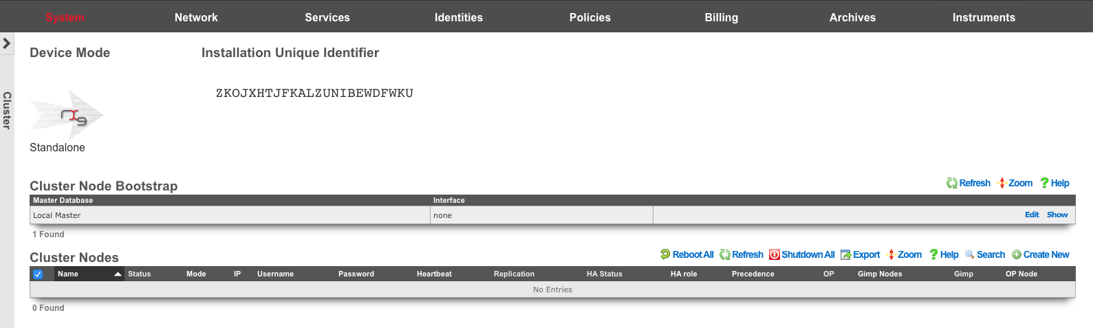
By default, the rXg stores its configuration database locally on the same hardware that executes the administrative console, portal web application, and enforcement engine. The rXg can be configured as part of a cluster using the Cluster Node Bootstrap scaffold of the Cluster view.
When operating as a node of a cluster , the rXg shares a remote database with all of its peers. By sharing a single database between all nodes, the operator uses a single, unified console to configure settings that are global to the cluster (e.g., end-user identity management, policy enforcement, etc.) as well as unique to the individual node (e.g., networking, SSL certificates, etc.). In addition, instrumentation and logging from all nodes in the cluster is centrally stored in the same shared database that resides on the cluster controller. This enables the operator to obtain complete cognizance over any end-user that is on any node of the cluster through the cluster controller administrative console.
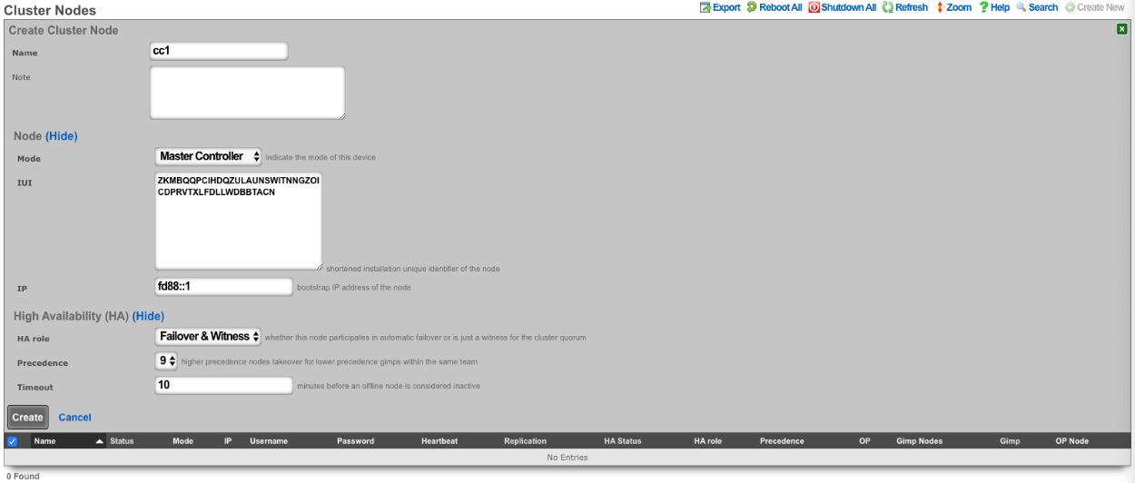
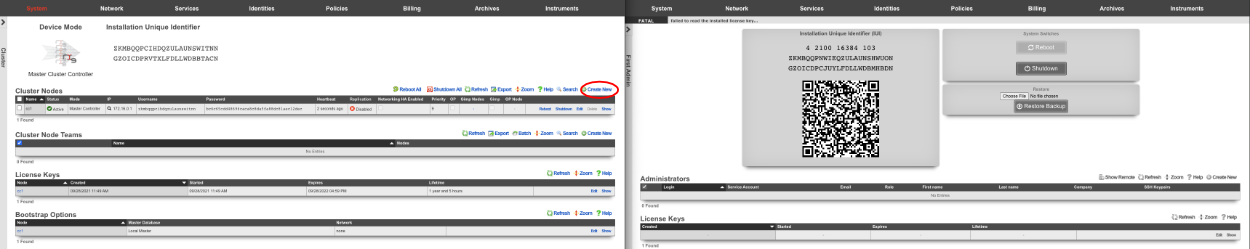
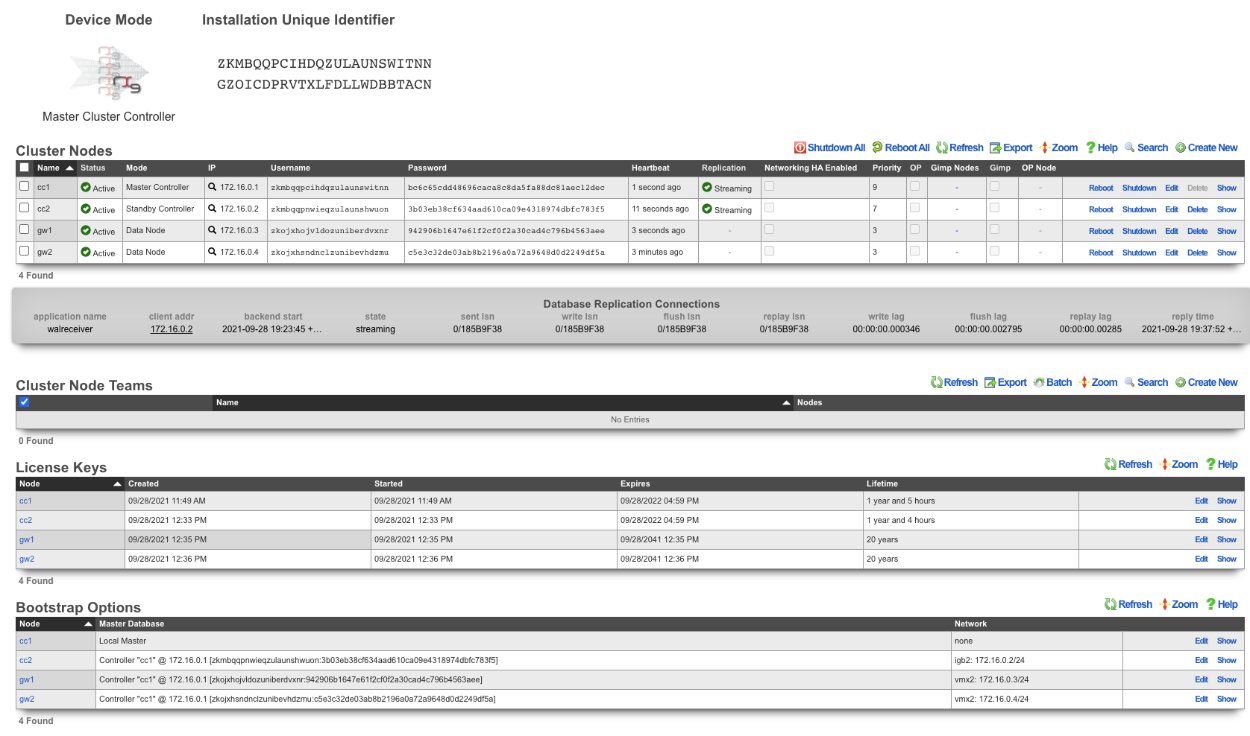
To enable an rXg as a cluster controller, the operator creates an entry in the Cluster Nodes scaffold. The first entry will always be for the master controller. Subsequent entries will be made for standby controllers and data nodes. The operator will need to provide the IUI, IP address, and HA Role for each subsequent system.
Each cluster should only contain one master controller entry which will contain the read-write copy of the database.
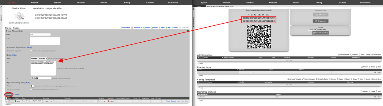
Standby controllers can be defined to receive read-only copies of the database and have the ability to promote to master controller in the event of a failure.
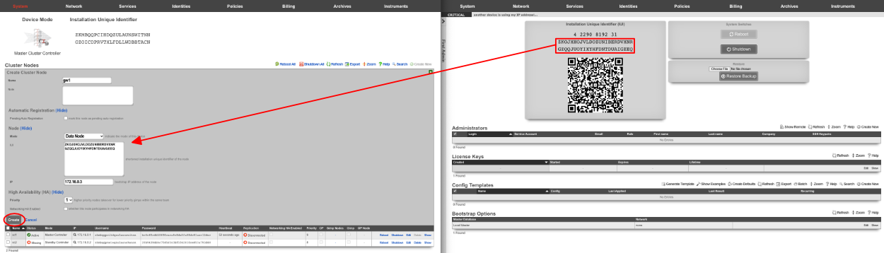
Data nodes contain no copy of the database and participate in the cluster by managing individual LAN segments.
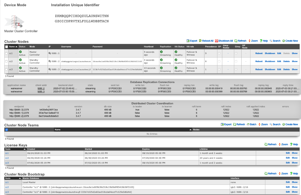
A cluster controller presents a Cluster Nodes scaffold on the Cluster view that configures the member nodes that are attached to the cluster controller. The operator must create a record for each and every cluster node that is to take part in a cluster managed by the cluster controller. Each record contains the credentials that authorize the cluster node to share the cluster controller database.
Deployment Procedure
A successful cluster deployment begins with a proper plan and documentation of the cluster topology. At very least, a network diagram must be created that has all relevant IP addresses labelled. Every cluster node must have at least three connections (LAN, WAN, CIN). The cluster controller must be connected to the CIN. The LAN and WAN connections are optional on the cluster controller , though recommended to ease remote and local access to the management console as well as enable ping targets for multiple uplink control.

- Install the rXg cluster controller(s), and all rXg cluster node hardware according to RG Nets guidelines.
- Power on the devices and connect to the administrative console of each device.
- Use the WAN IP address to connect to the administrative console as all units will have the same default LAN IP address at this time. If necessary, connect a serial terminal or VGA monitor to the rXg and hit CTRL-D to see what WAN IP address the rXg has acquired.
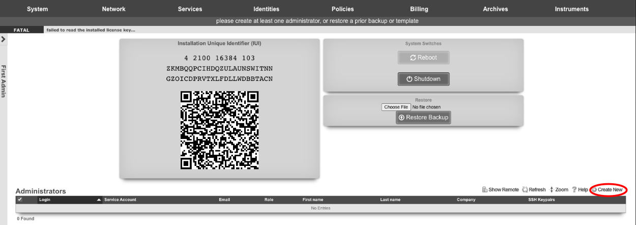
Create at least one administrator and install a valid license on the master controller.
On the master controller , bring up the LAN view and create an Ethernet interface along with an associated network address. This will define the CIN and allow all nodes to communicate with one another once configured.
Bring up two web browsers side-by-side. In one browser, open the administrative console of the cluster controller and navigate to the cluster view. You should see the Cluster Nodes scaffold with a single entry (the cluster controller ). In the second browser, bring up the administrative console of a cluster node (still in default state) and you should see the Cluster Node Bootstrap scaffold. The master database should be currently set to local master.
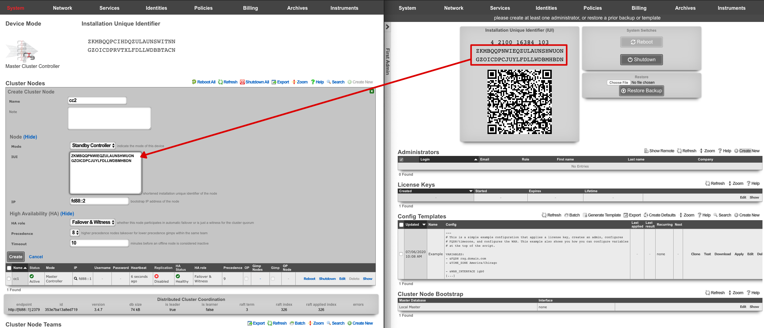
Create a new Cluster Node scaffold entry on the master controller by copying the IUI of the second system and defining the IP Address. Use the dual browser setup to repeat the process outlined here for each node that will take part in this cluster.
A new record in the Cluster Nodes scaffold must be created for every rXg device that will participate in this cluster.
- Copy the IUI from the browser displaying the cluster node console and paste it into the appropriate field displayed in the cluster node record creation form.
- Enter the CIN IP address that will be configured on this node into the IP field.
Choose the appropriate mode for the rXg device. Use the dual browser setup to repeat the process outlined here for each node that will take part in this cluster.
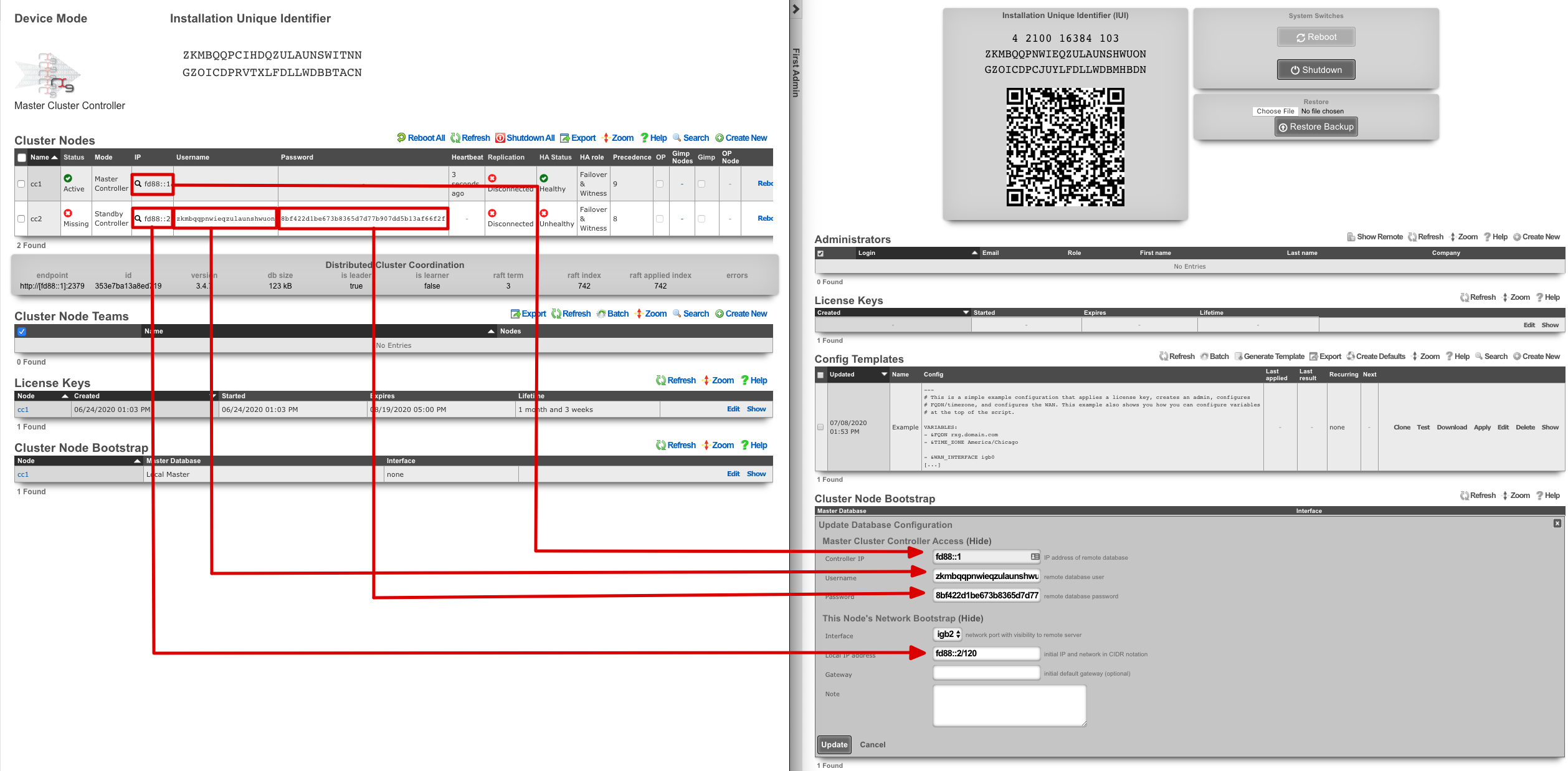
Click the edit link next to the record in the Cluster Node Bootstrap scaffold in the administrative console of the node. Enter the CIN IP address of the cluster controller in the Controller IP field. The settings for the username and password fields are displayed in the list view of the Cluster Nodes scaffold on the administrative console of the master controller. Copy and paste those values into the appropriate fields.
Choose the CIN port for the interface setting and enter the CIN IP address in CIDR notation for the cluster node into the local IP address fields. Click update to save the settings.
When the cluster node connects to the remote database on the cluster controller for the first time, a cluster node initialization process is automatically executed. First, the cluster controller incorporates the MAC addresses and media-types available to the cluster node into the set of all available Ethernet ports. Then, records for the CIN Ethernet interface and address are added to the cluster configuration and marked for application to the particular cluster node that is being initialized. In addition, a default device option for the new cluster node is created.
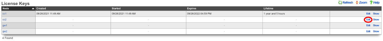
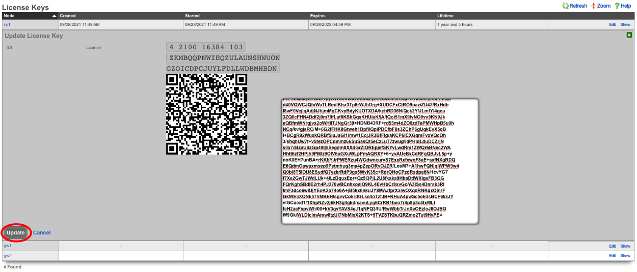
When all cluster nodes have been initialized, the deployment of the cluster is complete. The operator can input licensing for each node in the License Keys scaffold in the Cluster view. The cluster may now be configured with settings in a similar manner as a standalone rXg, by using the master controller administrative console.
Symmetric Cluster

In a symmetric cluster a node can operate as both the data plane and control plane. Because each node requires large, high endurance SSDs as well as enough CPU and RAM to operate as both the control plane and data plane, symmetric clustering is recommended for smaller deployments.
Asymmetric Cluster

An asymmetric cluster separates the control plane from the data plane. This enables the operator to scale requirements for nodes individually. Only nodes allocated as controllers need large high endurance SSDs, more CPU, and RAM. Data plane nodes require minimal SSD, CPU, and RAM to manage their individual LAN Segments.
All transit networking features are executed on the cluster nodes. The controller does not forward packets nor does it run any proxies for web experience manipulation. All billing, user management, and instrument collection features are executed on the cluster controller. Cluster nodes do not run recurring billing, system status, or traffic rate collection tasks.
Data Flow: Control Plane / Data Plane Communication
The following diagram illustrates the communication flows between cluster components during normal operation. The Master Controller (control plane) manages configuration and persistent storage, while Data Nodes (data plane) handle packet forwarding, DHCP, NAT, and policy enforcement for their assigned LAN segments. Standby Controllers maintain hot-standby database replicas for high availability.
Cluster Sync and Configuration Push
sequenceDiagram
    participant Op as Operator<br/>(Admin Console)
    participant MC as Master Controller<br/>(Control Plane)
    participant PG as PostgreSQL<br/>(Master DB)
    participant SC as Standby Controller<br/>(Hot Standby DB)
    participant DN as Data Node<br/>(Data Plane)

    Note over Op,DN: Configuration Change Flow

    Op->>MC: Save configuration change<br/>(e.g., create Policy, VLAN, Address)
    MC->>PG: Write to database<br/>(INSERT/UPDATE)
    PG-->>MC: Commit confirmed

    par WAL Streaming Replication
        PG->>SC: Stream WAL records<br/>(continuous async replication)
        SC-->>PG: Acknowledge LSN position
    and TriggerCallbacks to Data Nodes
        MC->>DN: TriggerCallback via CIN<br/>(notify config change)
        DN->>PG: Read updated config<br/>(SELECT over CIN)
        PG-->>DN: Return config records
        DN->>DN: Apply config locally<br/>(regenerate PF rules,<br/>update DHCP, NAT tables)
        DN-->>MC: Acknowledge sync complete
    end

    Note over Op,DN: Instrumentation Collection Flow

    loop Every collection interval
        DN->>DN: Collect local metrics<br/>(traffic rates, connection states,<br/>DHCP leases, NAT assignments)
        DN->>PG: Write instrumentation data<br/>(INSERT over CIN)
        PG-->>DN: Commit confirmed
    end

    Op->>MC: View Instruments dashboard
    MC->>PG: Query instrumentation tables
    PG-->>MC: Return aggregated metrics<br/>(collated across all nodes)
    MC-->>Op: Display cluster-wide instruments
Heartbeat Monitoring and HA Failover
sequenceDiagram
    participant MC as Master Controller
    participant SC as Standby Controller
    participant DN1 as Data Node 1
    participant DN2 as Data Node 2
    participant W as Witness<br/>(Quorum)

    Note over MC,W: Normal Operation - Heartbeat Exchange

    loop Heartbeat cycle
        MC->>DN1: Heartbeat ping via CIN
        DN1-->>MC: Heartbeat response<br/>(update heartbeat_at)
        MC->>DN2: Heartbeat ping via CIN
        DN2-->>MC: Heartbeat response<br/>(update heartbeat_at)
        MC->>SC: Heartbeat ping via CIN
        SC-->>MC: Heartbeat response
        MC->>W: Heartbeat ping via CIN
        W-->>MC: Heartbeat response
    end

    Note over MC,W: Data Node Failure Scenario

    MC->>DN1: Heartbeat ping via CIN
    DN1--xMC: No response (node failure)

    loop HA timeout period (default 300s)
        MC->>DN1: Retry heartbeat
        DN1--xMC: No response
    end

    MC->>MC: HA timeout exceeded<br/>for DN1
    MC->>DN2: Take over DN1 networking<br/>(L2s, L3s, VLANs, addresses)
    DN2->>DN2: Configure DN1 interfaces<br/>(bring up failover networking)
    DN2-->>MC: Networking takeover complete
    MC->>MC: Generate health notice<br/>(Cluster Node Status)

    Note over MC,W: Controller Failover Scenario

    MC--xSC: Master becomes unreachable

    loop Control Plane HA backoff (default 300s)
        SC->>MC: Attempt connection
        MC--xSC: No response
    end

    SC->>W: Request quorum vote
    W-->>SC: Quorum granted
    SC->>SC: Promote PostgreSQL<br/>(pg_ctl promote)
    SC->>SC: Assume Master Controller role
    SC->>DN1: Resume heartbeat monitoring
    SC->>DN2: Resume heartbeat monitoring
CIN Traffic Summary
All inter-node communication traverses the Cluster Interconnect Network (CIN), a dedicated gigabit Ethernet segment. CIN traffic passes through the policy enforcement engine unfettered (no packet filter states, no queuing). The following traffic types flow over the CIN:
| Traffic Type | Direction | Description |
|---|---|---|
| PostgreSQL WAL | Master Standby | Streaming replication of database write-ahead log records |
| Database queries | Nodes Master | Config reads and instrumentation writes from data nodes |
| TriggerCallbacks | Master Nodes | Notifications of configuration changes requiring local application |
| Heartbeat | Master All Nodes | Liveness monitoring for HA failover decisions |
| BNG Entry Sync | Nodes Master | MAC-to-VLAN tag mappings learned at the data plane |
| RADIUS Proxy | Nodes Master | Proxied RADIUS requests when enable_radius_proxy is set |
Implementation Details
The gateway setting in the Cluster Node Bootstrap scaffold of cluster nodes should not be configured unless absolutely necessary. Setting this implies that the cluster node will connect to the cluster controller via an uplink interface and is not officially supported.
All CIN traffic is passed through the rXg policy enforcement engine unfettered. No packet filter states are created and traffic is not queued. Ensure proper cluster operation by making sure that the CIN is properly deployed using high performance gigabit Ethernet equipment and high-quality cables.
A valid license must be present in the license view of the cluster controller for every node associated with the cluster.
Device and network configurations are associated with a particular node while almost every other kind of configuration is global. If a scaffold does not have a field that associates a node with the record, the record will apply globally to the entire cluster. When the scaffold has an active setting, only one record per cluster node may be made active. The records that are not active are shared by the cluster.
When configuring Ethernet interfaces , one port will be available for each physical port in the cluster. Since all networking configuration (e.g., addresses , uplinks , VLANs , binats and even all the DHCP server settings) are ultimately linked to an Ethernet interface , the port field determines which node the configuration applies to.
A single uplink control record may contain uplinks that span several nodes of the cluster. However, on each node, only the relevant uplinks are used to determine the weighted connection pools.
Ping targets may be configured as node-specific (associated with a cluster node record). Ping targets that are node-specific are pinged and status-updated by their associated node only.
Ping targets that have no cluster_node association are global to the cluster. Global ping targets are status-updated by only the cluster controller. However, global ping targets may and should be used to instrument the condition of multiple uplinks configured throughout devices in the cluster. In this case, all nodes having an uplink associated with the global ping targets ping the target through the respective uplink(s), but only the online state of the uplink record is changed, not the state of the global ping target itself, except by the controller. Creating a ping target with an uplink(s) association automatically clears any cluster node associated with it.
System graphs must be cluster node specific and represent data for only that node or the cluster controller.
Network graphs are global. Graphs of IPs , MACs , login sessions , bandwidth queues , and policies represent cluster-wide data. For example, traffic rate stats for the same IP that may somehow be behind two different nodes is accumulated at the controller and collated into a single database entry for that IP. Similarly, traffic rates statistics for a single bandwidth queue or policy are collected from all nodes, summed at the controller, and written to a single database entry. Cluster node specific items defined by the records that are directly or indirectly associated with an Ethernet interface record are stored in node specific records.
Cluster Node Bootstrap
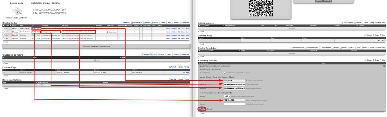
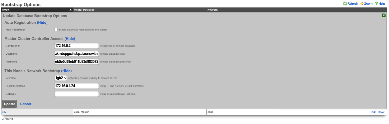
The Cluster Node Bootstrap scaffold configures the mechanism by which this rXg will join a cluster.
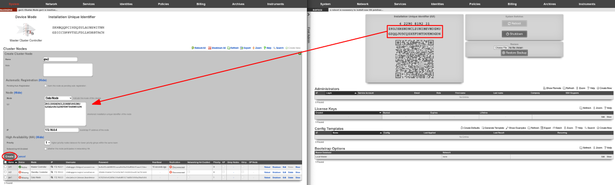
The controller IP field specifies the IP address of the rXg cluster controller.
The username and password fields are the credentials assigned to this node by the cluster controller. Obtain the values for these fields by entering the IUI for this node into the Cluster Nodes scaffold of the Cluster view on the console of the cluster controller.
The interface field configures the Ethernet interface that will be used by this cluster node to communicate with the cluster controller. An Ethernet interface must be dedicated for the sole purpose of cluster communications.
The local bootstrap configuration options ( local IP address and gateway ) are used as the bootstrap configuration of the rXg when operated in cluster mode. This is needed to enable the cluster node to communicate with the cluster controller and retrieve the complete rXg configuration from the controller.

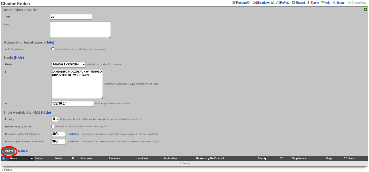
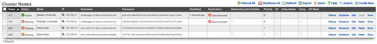
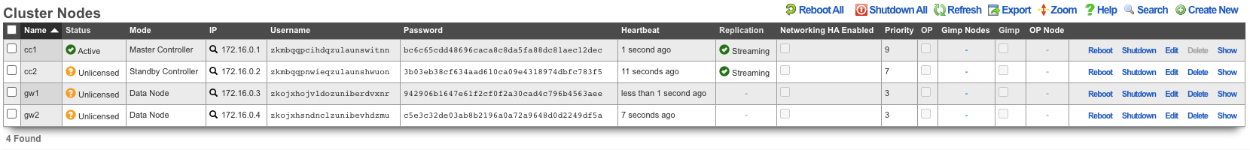
Cluster Nodes
Cluster nodes define the members of an rXg cluster.
The name field is an arbitrary string descriptor used only for administrative identification. Choose a name that reflects the purpose of the record. This field has no bearing on the configuration or settings determined by this scaffold.
The note field is a place for the administrator to enter a comment. This field is purely informational and has no bearing on the configuration settings.
The auto registration box enables automatic registration of cluster nodes. Allows for automatic cluster configuration.
The permit new nodes box allows new nodes that have never been a member of the cluster to join the cluster.
The auto approve new nodes box allows new nodes to be automatically approved without operator intervention.
The pending auto registration box, if checked, will mark the node as pending auto registration. When the node connects to the master controller for the first time it will automatically become a member of the cluster.
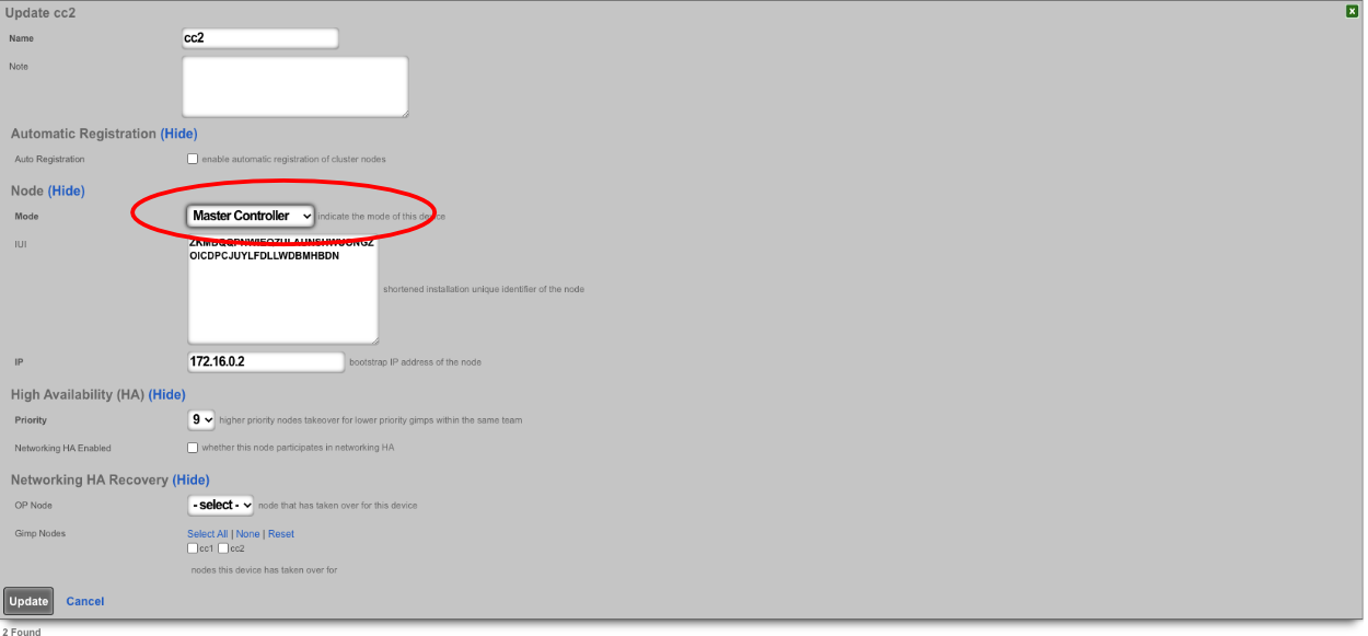
The mode dropdown indicates the type of node defined by this record. Only one node may be defined as the master controller for each cluster.
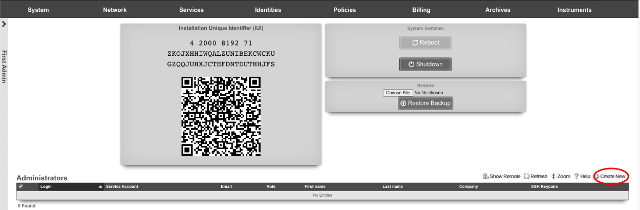
The IUI is the installation unique identifier for the node that is defined by this record. The installation unique identifier for an rXg may be found by visiting the license view of the system menu.
The IP is the IP address that will be used by the cluster node for communicating with the cluster controller. This will also be the bootstrap IP address that is configured in the Cluster Node Bootstrap scaffold of the Cluster view on the cluster node.
The priority field indicates the priority of an individual node. A higher precedence node takes over for lower precedence gimps (failed nodes) within the same team.
The DP (data plane) HA enabled field defines the HA behavior of this node in the cluster; if checked this node will take over networking for a failed node, if unchecked the node will not.
The control plane HA backoff (seconds) field specifies the amount of time a node will try to reach the controller before moving on to the next controller. Default value is 30 seconds.
The DP (data plane) HA timeout (seconds) field specifies the amount of time that must elapse before a node is considered offline, and another node will take over the networking configured on the failed node. Default value is 300 seconds.
The username and password fields are the credentials assigned to this node by the cluster controller. Enter these into the cluster view of the appropriate cluster node to enable access.
Example Cluster Setup: 2 CC's, 2 GW's
For this example, there will be 4 machines: 2 CC's and 2 GW's. For different cluster layouts there may be more CC's or GW's. The example below will provide details on adding each type. The first step will be to install the rXg software on all 4 machines. Once this is done, two browser windows should be opened: one for the primary CC, and the 2nd for all additional nodes (this includes any CC's or GW's that will be added).
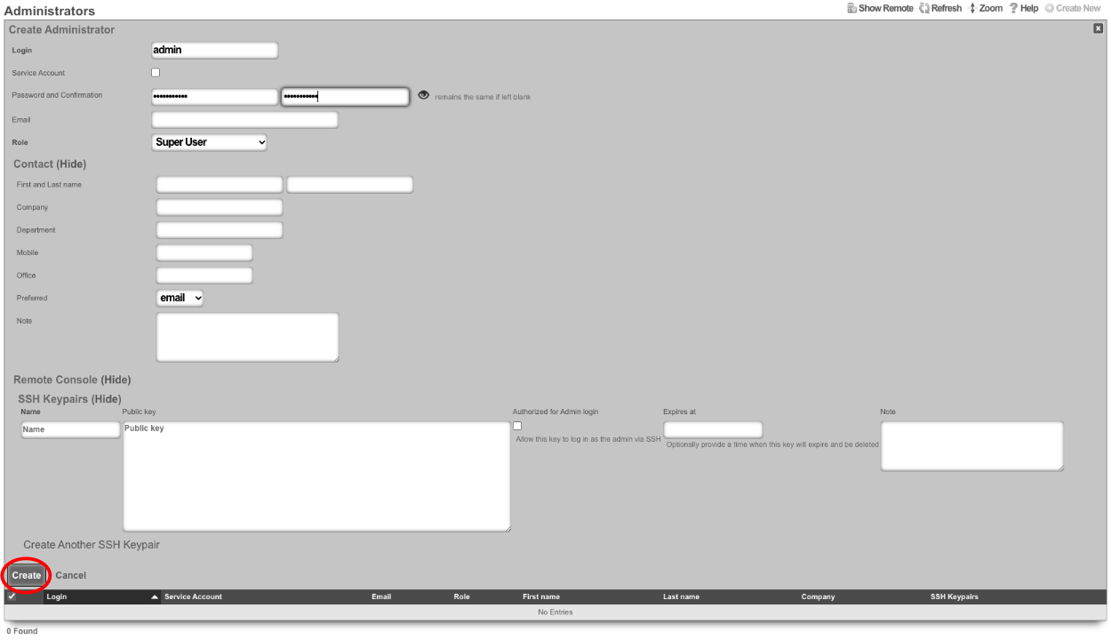
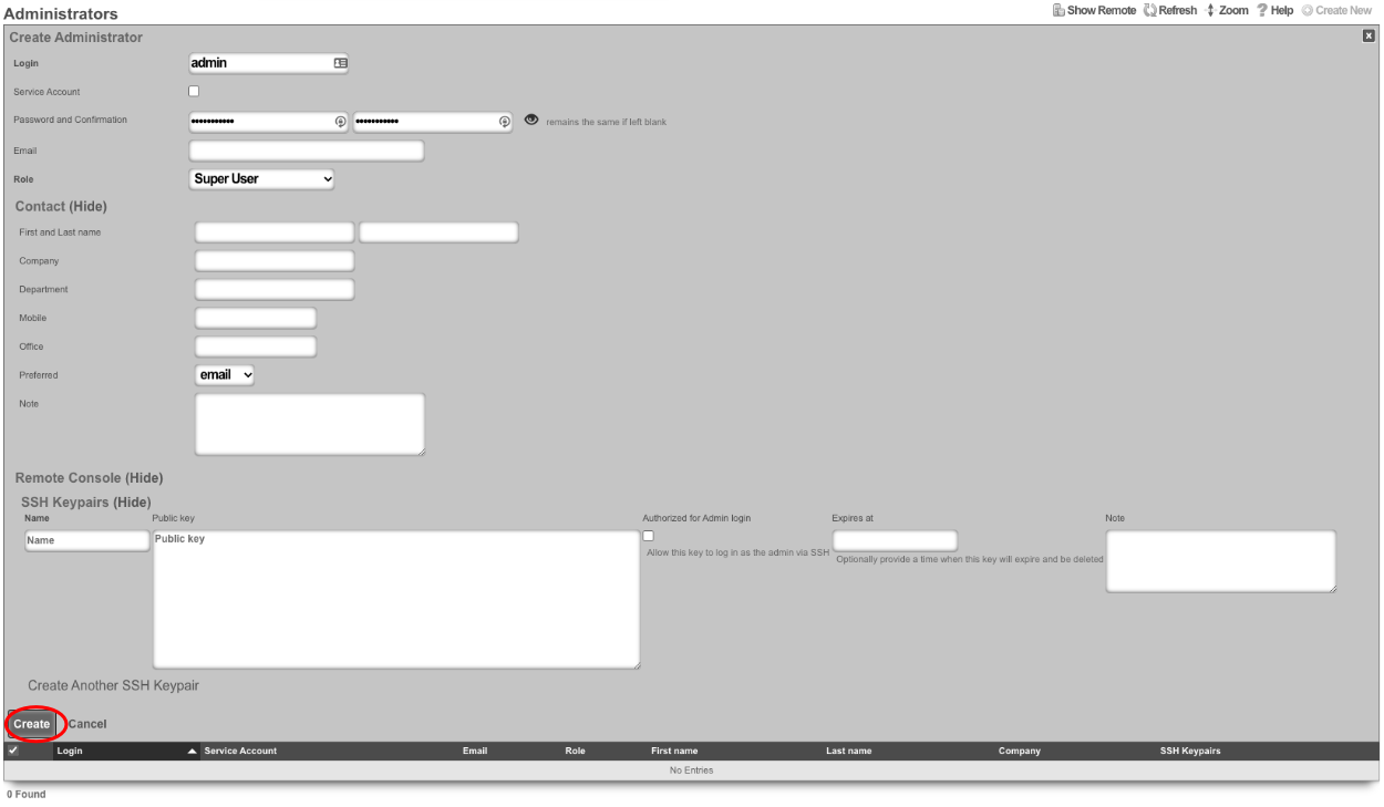
Create a new administrator on the Master Controller , by clicking "Create New" on the Administrators scaffold. Each admin account should be unique for every operator.
At a minimum a Login and Password are required. Click create.
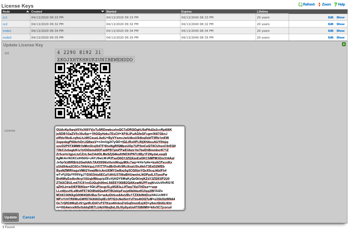
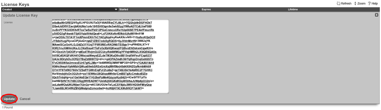
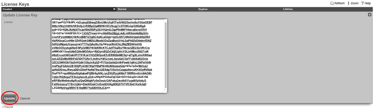
Next edit the License Keys scaffold.

Paste in the license key and click update. This will restart the webserver.
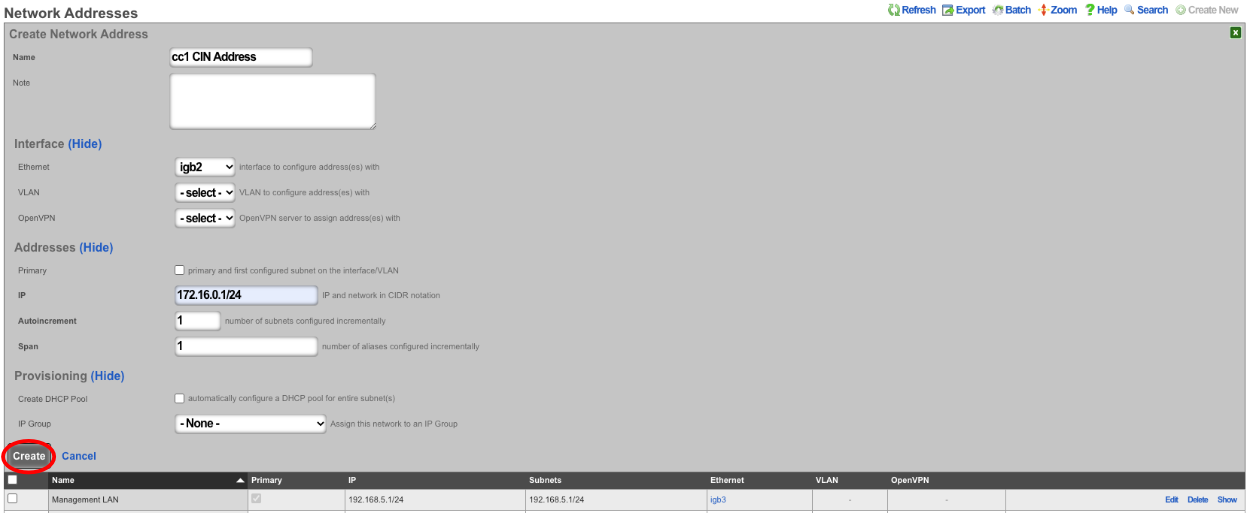
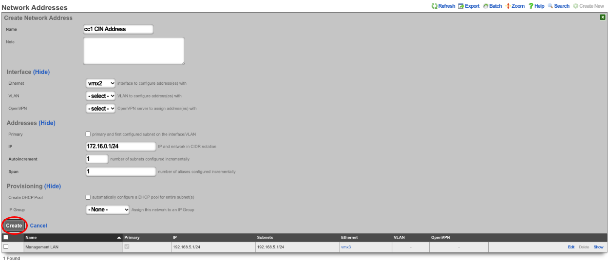
Next the CIN (Cluster Interconnect Network) will be created. Navigate to Network::LAN , and create a new network address.

Name: cc1 CIN Address. Set the interface , and specify the IP address in CIDR notation. Leave both autoincrement and span values at 1. Do not check create DHCP pool. Click create.
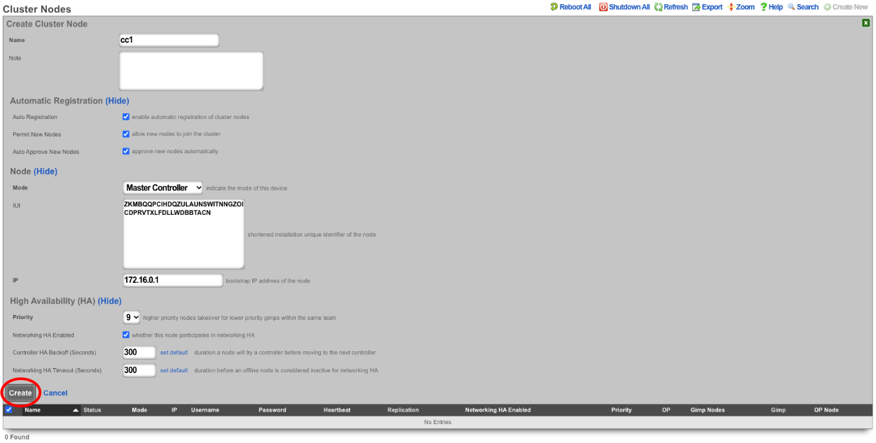
Turn rXg into Master Controller by navigating to System::Cluster. Create a new cluster node by clicking create new on the Cluster Node scaffold.
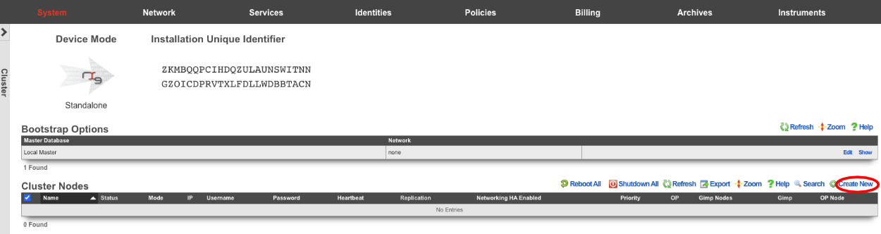
Uncheck DP (data plane) HA enabled this will ensure that the CC doesn't take over the networking for the other nodes before they are integrated into the cluster. Verify that the default information is correct and click create.
Create a new cluster node record for each CC and GW that will be added to the cluster. The easiest way to do this is to have 2 browser windows open, one with the Master Controller admin GUI loaded, and the other with the admin GUI with a tab for each CC and GW. Click create new on the Cluster Nodes scaffold.
Verify the name and mode is correct. Copy the IUI from the secondary controller into the IUI field on the Master Controller , verify that the mode , IP , and priority are configured as desired. Uncheck the DP (data plane) HA enabled box. Click create.
Next repeat for the 2 GW nodes. Click create new on the Cluster Nodes scaffold, copy the IUI from the first GW node into the IUI field. Verify that the mode , IP , and priority are configured as desired. Uncheck the DP (data plane) HA enabled box. Click create.
Repeat for GW 2. Verify that the mode , IP , and priority are configured as desired. Uncheck the DP (data plane) HA enabled box. Click create.
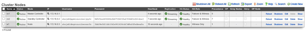
All the CC's and GW's now have cluster node records on the Master Controller.
Next, we will integrate the secondary CC and GW's into the cluster using the Cluster Node Bootstrap scaffold. On the secondary cc admin GUI in the second browser edit the cluster node bootstrap record.

Copy controller IP , username , password from the Master Controller's Cluster Nodes scaffold to the secondary controller. Set the interface , and the local IP address in CIDR notation. Click update.
Repeat the process for GW 1 and GW 2 nodes.
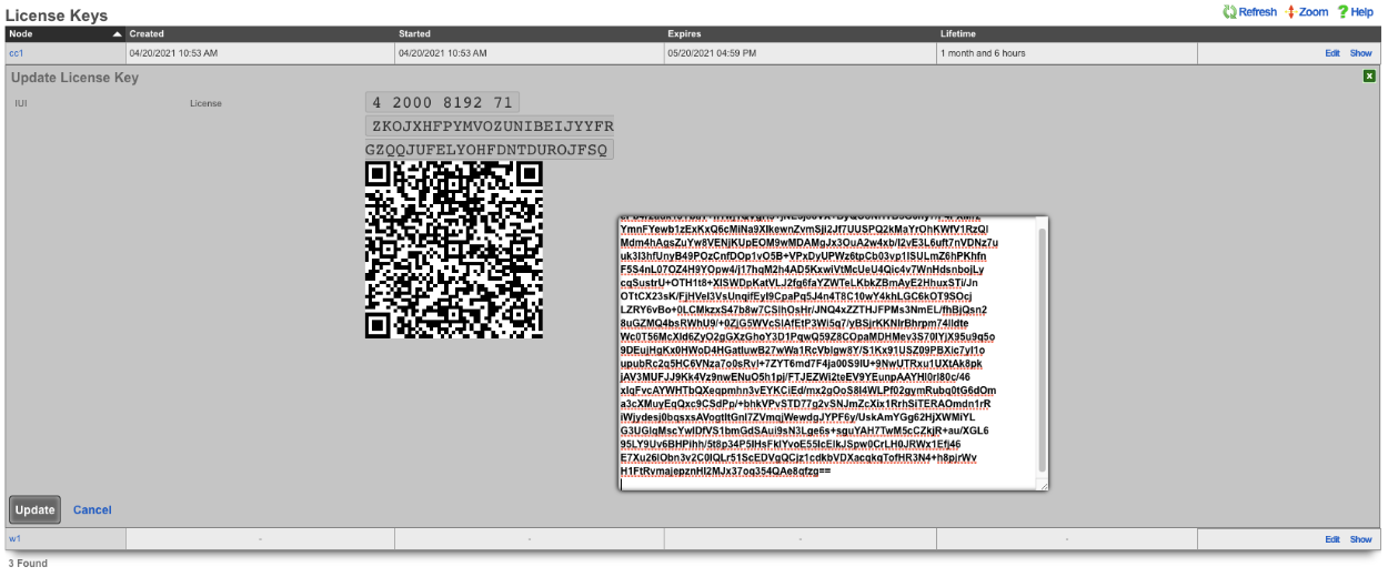
Next add the license for each node. On the Master Controller edit the license key entry for cc2 paste the license in. Repeat for each node.
After the licenses have been installed on the remaining nodes the cluster configuration is complete. The operator will now use the Master Controller to continue configuring the system. The System::Cluster page will now show Replication and HA status as green.
Example Cluster Setup: Using Autoconfiguration 2 CC's
For this example, we will use auto configuration to configure a cluster consisting of 2 CC's. Unlike the previous example, we will use the auto configuration option instead of manually creating the cluster. After installing the rXg software on each machine, open a separate browser tab for each machine in the cluster.
Create a new administrator on the Master Controller , by clicking "create new" on the Administrators scaffold. Each admin account should be unique for every operator.
At a minimum a login and password are required. Click create.
Next, edit the License Keys scaffold.

Paste in the license key and click update , this will restart the webserver. Note: if an asset exists in the licensing portal with the IUI of the node, the node will automatically retrieve its license.
Next the CIN (Cluster Interconnect Network) will be created. Navigate to Network::LAN, and create a new network address.

Name : cc1 CIN Address. Set the interface , and specify the IP address in CIDR notation. Leave both autoincrement and span values at 1. Do not check create DHCP pool. Click create.
Turn the rXg into a Master Controller by navigating to System::Cluster. Create a new cluster node by clicking create new on the Cluster Node scaffold.

Verify that the default information is correct. Check the auto registration box, this will allow the automatic registration of cluster nodes. Once that is done, it will open up the permit new nodes option, check this as well. This will allow new nodes to join the cluster so they can auto-register.
Now the auto approve new nodes option will become available. Check this box. By checking this box, the operator of the rXg will not need to approve new nodes that join the cluster. Checking all the boxes makes it so new nodes will not only auto join the cluster but will also be approved without any intervention. If you wish to disallow the auto-approval process, then the opererator will need to approve each node before it will become part of the cluster.
For this example, we are checking all the options so that the process is as automatic as possible. Click create.
Now go to the tab that was opened with the secondary CC's admin GUI. Do not create an admin or apply a license at this time. Scroll down to the bottom of the page and edit the cluster node bootstrap record.

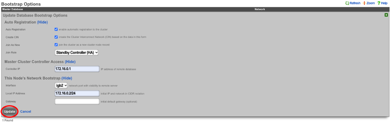
Under the Auto Registration section check the auto registration box, which will enable the node automatically register to the Master Controller. This will unlock the create CIN option and the join as new option. Create CIN will create the cluster interconnect network on the node using the data provided on the form. Check the create CIN box.
The join as new box should be checked if this node has never been a member of this cluster before (such as having a node fail and re-adding it to the cluster after repair - it would not be a new node in this case), check this box. This will allow the operator to select the join role for this node. In this case, it should be set to*standby controller (HA)*.
Enter the controller's IP address in the controller IP field. Set the interface that will be used to connect to the CIN network in the interface field. Set the CIN IP of this node in the local IP address field. The gateway field does not need to be set because the node belongs to the same network as the Master Controller. Click update.
The cluster node bootstrap record will now show that it is awaiting auto-registration.

On the Master Controller navigate to System::Cluster. Both nodes should not be listed in the Cluster Nodes scaffold.

Note that their status may be unlicensed; the licenses can be added via the License Key scaffold below. Edit the record for CC2 and paste in the license. In this case, the nodes have pulled their licenses automatically.
Now that the licenses have been added, it is a fully functional cluster that created itself without the operator needing to copy and paste information between the Master Controller and nodes.
How to change which Cluster Controller is the Master Controller
Turn off DP (data plane) HA on the nodes, leave the Master Controller for last.
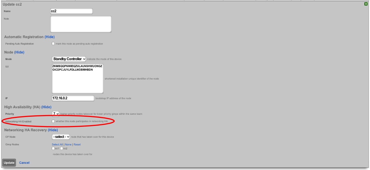
Make sure the priority of the standby you want to become the new master is higher than all other standby controllers. Typically, the standby controllers will be a priority of 7 by default. Set the standby that you want to be master to 9.

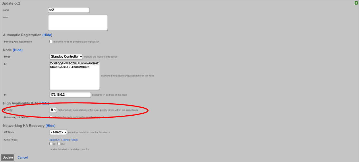

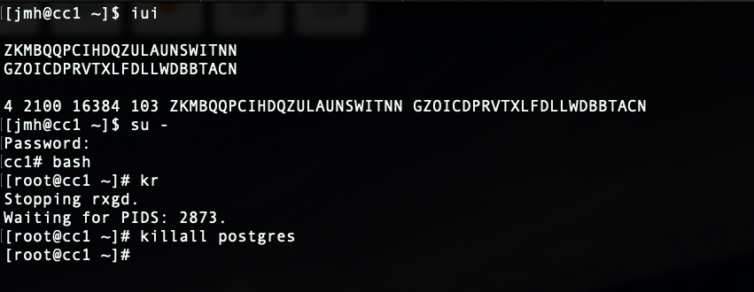
SSH into the current master. Stop rxgd and kill postgres (you will need to become root for this). Running ' kr' will stop rxgd and then running ' killall postgres' will stop postgres. Once this is done, the highest priority standby will take over as master. You can reduce the HA timeout to make this faster (default is 5 minutes).
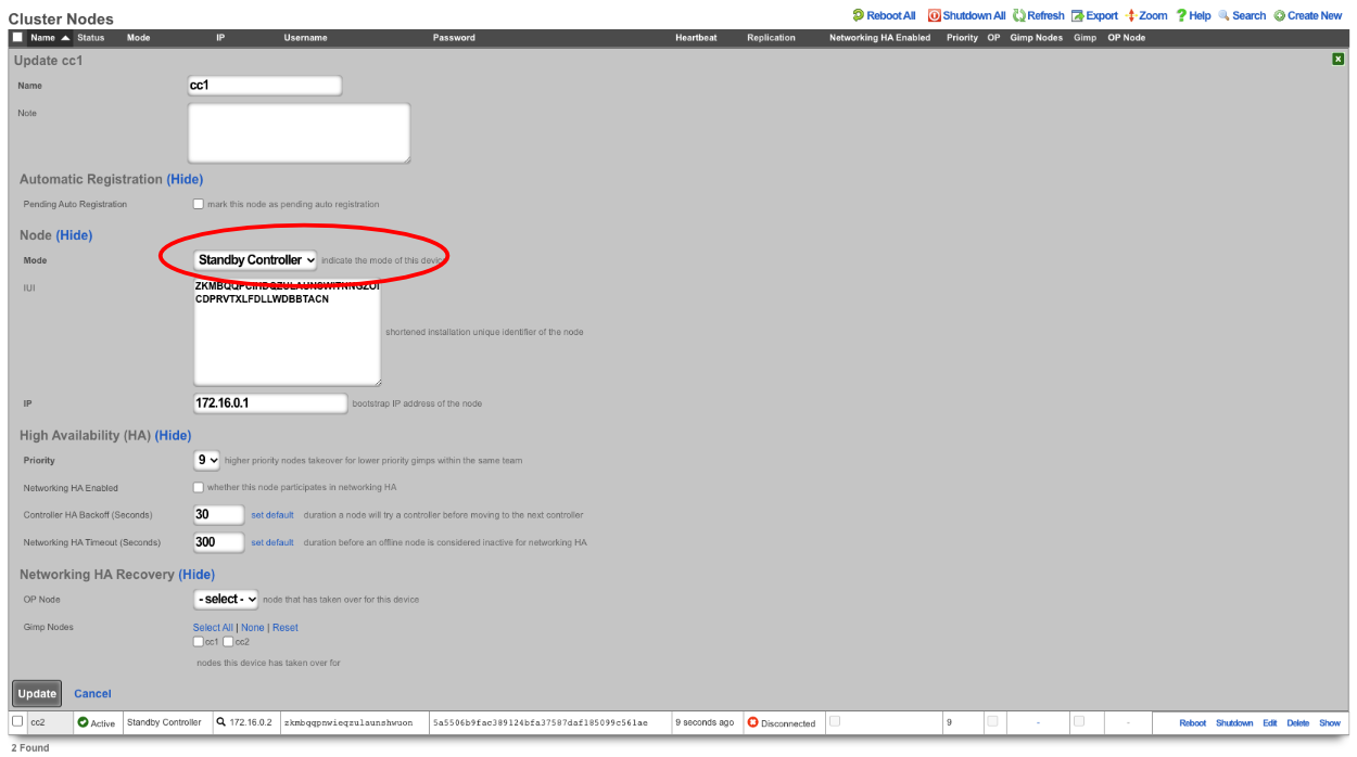
Open GUI on the new master. Edit the cluster node record for the current master node and set to standby.
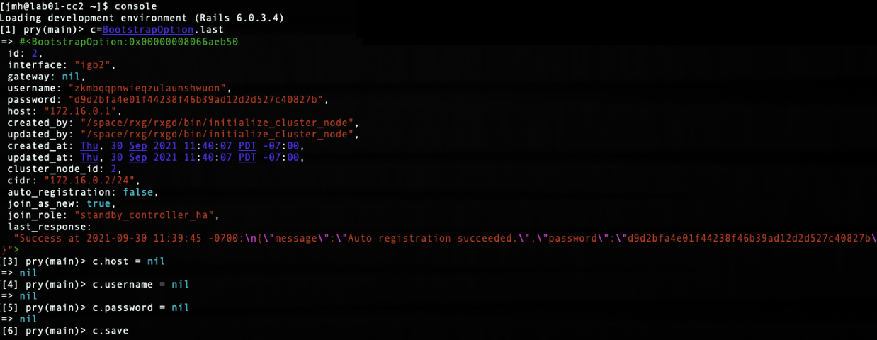
SSH into the node that will be the new master. Run ' console' to access the rails console. Find the BootstrapOption record for the NEW master and set the host , username , and password fields to nil. In this case, the record that will be edited is the last record, since there is only CC1 and CC 2. The record can be found by running ' BootstrapOption.last'.
Edit cluster node record in GUI for new master and set to master.
Edit the bootstrap option record in GUI for old master and set it as if it is a new node.
SSH to OLD master and edit the bootstrap.yml located at /space/rxg/bootstrap.yml. Change the order under _controllers so that the NEW master is on top of the list followed by any other standbys. Repeat for bootstrap_live.yml. After editing the 2 files on the OLD master run ' rr' to restart rxgd. If you changed the control plane HA timeout , be sure to set it back. Finally, edit the cluster node records and re-enable DP (data plane) HA , doing the master CC last.

Note: Doing this will not copy over graphing information so it will be lost.
Node Integration After Failure
With HA 3.0 , the process to get a failed node back into the cluster is straight forward. For example, if a node loses a power supply, once it's replaced and the node is turned back on, the node will automatically join the cluster and take over networks configured on it (if another node took over for it).
If the node is replaced with new hardware, meaning the IUI has changed, the cluster node record for the downed node can be edited. Once the IUI is replaced with the new node's IUI , the username and password for the new node will be generated. These can then be entered into the bootstrap and the node will integrate into the cluster and replace the failed node.


