LAN
The LAN view presents the scaffolds associated with configuring the local area network interfaces.
An rXg requires at least one properly configured LAN address in order to function. To configure an IP address on an interface, create a record in the addresses scaffold and associate it with an Ethernet interface record. If the LAN distribution network is connected via an 802.1Q VLAN trunk, create VLAN interfaces using the VLANs scaffold and then associate address records with the VLAN interfaces.
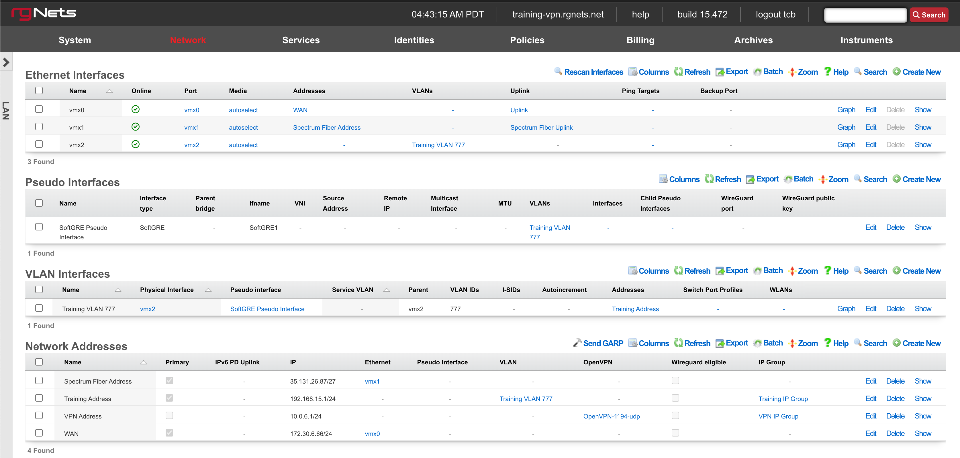
Ethernet Interfaces
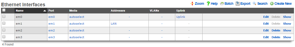
An entry in the ethernet interfaces activates and configures a physical port on the rXg to take part in in networking connectivity.
In most cases, at least two ethernet interfaces must be configured (one for the WAN, one for the LAN). In multiple uplink scenarios, it is common to have one ethernet interface configured for each WAN uplink. It is also possible to use VLANs on a single ethernet interface to configure unlimited WAN and LAN interfaces.
The name field is an arbitrary string descriptor used only for administrative identification. Choose a name that reflects the purpose of the record. This field has no bearing on the configuration or settings determined by this scaffold.
The port field determines the physical ethernet port that this record will activate and configure.
The media field configures the speed and duplex of the Ethernet port. In most cases, the autoselect setting will automatically negotiate the fastest possible link. Autoselect should also be used if automatic crossover detection is required as most Ethernet hardware will disable automatic crossover if anything other than autoselect is specified as the media type.
If physical link cannot be established, first check the physical cable using an isolation test. If the cable is determined to not be the issue, try setting the ethernet interfaces on both sides of the cable to the same speed and duplex. Note that if a straight cable is connected between two nodes, that cable will need to be replaced with a crossover because automatic crossover detection will be disabled when a media type other than autoselect is specified. In addition, using a lower speed setting and avoiding full-duplex communication may be necessary when the cable is long or does not meet the standards needed for higher speed communication.
The MTU setting configures the maximum transmission unit (frame size) for this interface. By default, most ethernet interfaces support 1500 bytes. Large MTUs may be used in gigabit networks that support jumbo frames to obtain better throughput when transferring large files. Support for jumbo frames must be present throughout the infrastructure in order for larger MTUs to work properly.
The addresses , uplink , VLANs and PPPoE fields link an Ethernet interface to a configuration defined by the specified scaffold. These fields shown here are mainly presented for informational purposes. In most scenarios, an administrator will link the address, uplink, VLAN or PPPoE configuration to the Ethernet interface using the other scaffold.
The backup port field specifies an alternative ethernet interface to assign the addresses , uplink , VLANs and PPPoE configuration settings when this ethernet interface goes down. An ethernet interface is marked as down if it loses link or if all of the ping targets associated with it go offline. The VLANs and Network Addresses associated with an ethernet interface are moved to the backup port when the ethernet interface is marked as down. The backup port mechanism is designed to be used with generic L2 switching. Backup ports should not be used with any LAG/MLT/SMLT/LACP configuration on the connected switch.
The checksum offload , TCP segmentation offload and large receive offload settings offload the specified processing to the NIC hardware when possible. In some cases this may cause instability and in other cases there are performance benefits.
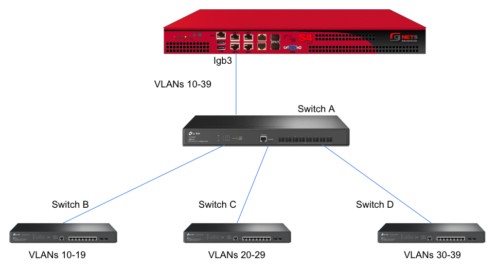
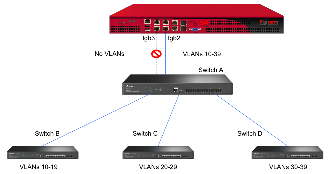
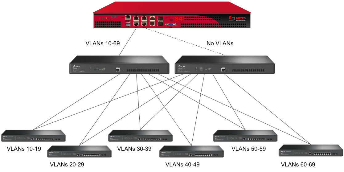
In this example, there is no redundancy as there is only one path between the rxg and all network switches. If the rxg loses connectivity with Switch A, Switch B, C, and D will also lose access.
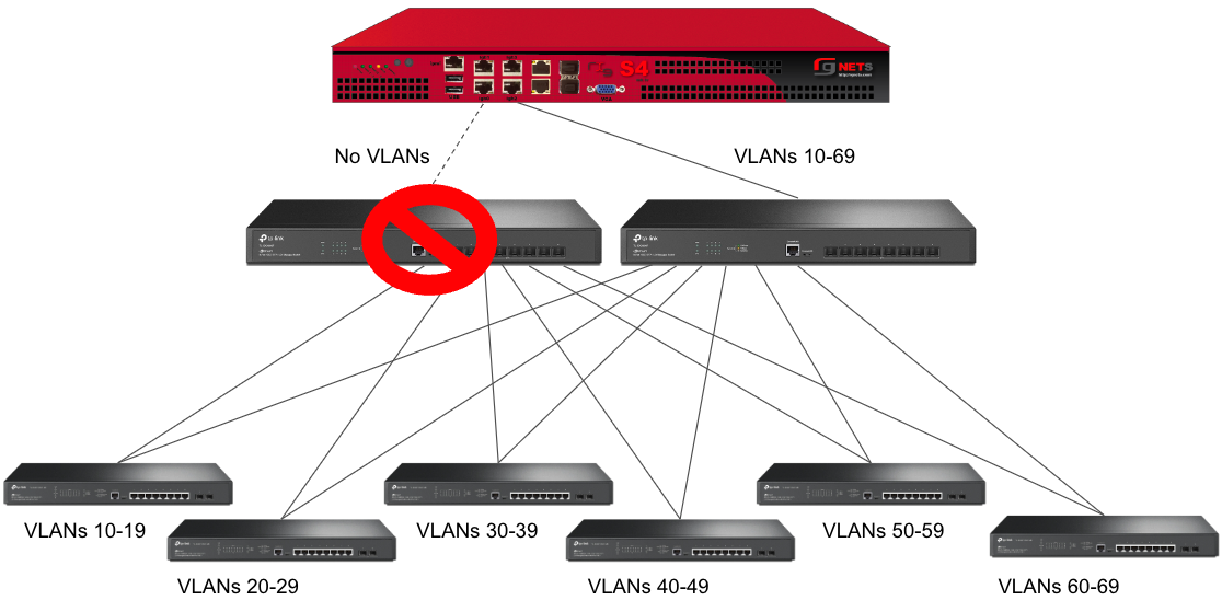
A slightly better version of the above configuration would be to add a Backup Port so that if the primary link to switch A becomes unusable, a secondary link can be utilized.
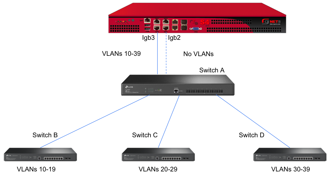
Edit the primary interface, select several Ping Targets , then select a Backup Port.
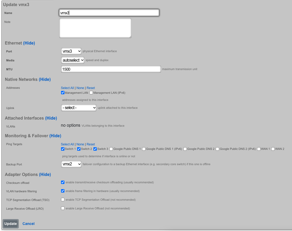
In this example, when Igb3 loses link or all Ping Targets fail to respond, the VLANs and Network Addresses associated with Igb3 are moved to the Backup Port Igb2. Igb3 is marked as down.
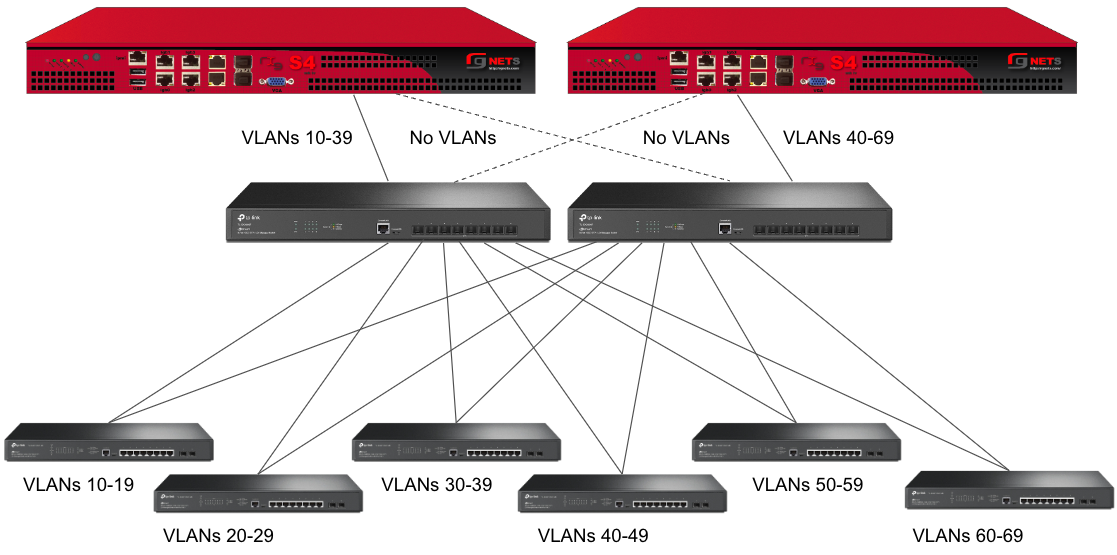
However, this still leaves Switch A as a single point of failure. Consider the below topology for a higher level of redundancy.
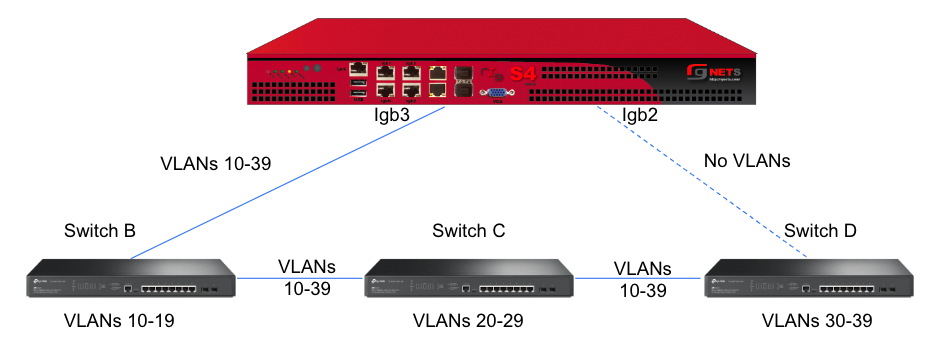
This feature is not dependent on proprietary protocols and as such will work with most any available switch.
Sample Topology: Redundant Core Switches
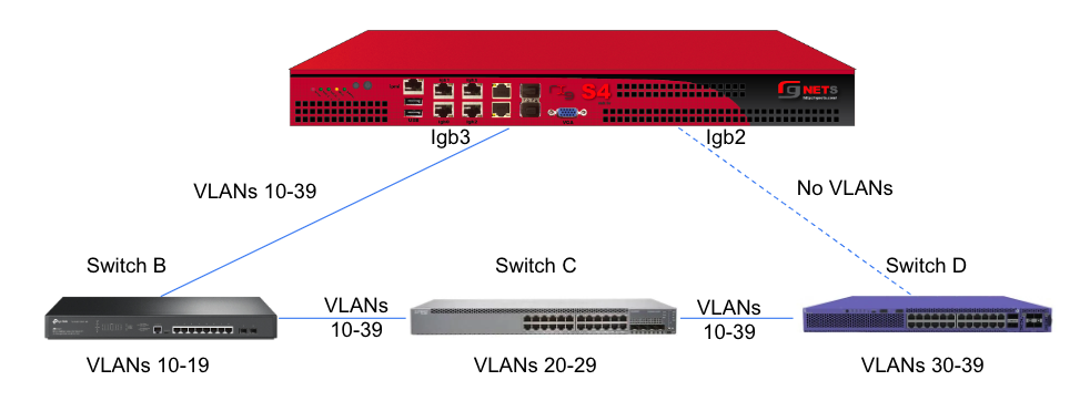
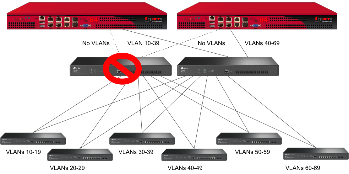
Sample Topology: Redundant Gateways and Core Switches
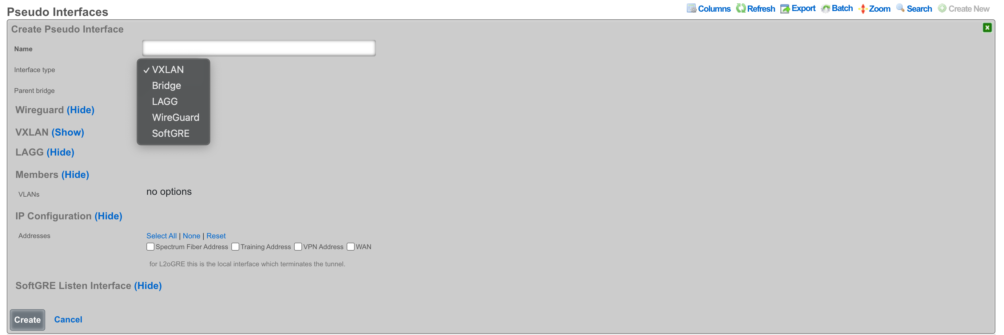
Pseudo Interfaces
Pseudo interfaces provide virtual network interface capabilities that extend beyond traditional physical interfaces. These software-defined interfaces enable advanced networking features including tunneling, aggregation, and virtualization. The rXg platform supports multiple pseudo interface types, each optimized for specific use cases and deployment scenarios.
General Features and Capabilities
Parent/Child Pseudo Interface Relationships
The rXg platform supports sophisticated hierarchical relationships between pseudo interfaces, enabling operators to create complex network topologies that mirror real-world deployment scenarios. This capability allows a parent pseudo interface to contain and manage multiple child pseudo interfaces, establishing a tree-like structure that simplifies management and enhances scalability.
When configuring parent/child relationships, the parent interface acts as a container that aggregates the functionality of its children. This architecture proves particularly valuable in bridge configurations where multiple pseudo interfaces need to operate as a cohesive unit. The parent interface inherits certain properties from its children while maintaining its own distinct configuration parameters. Traffic flowing through child interfaces can be managed collectively at the parent level, enabling centralized policy application and traffic shaping.
The relationship between parent and child interfaces operates bidirectionally in terms of configuration inheritance. Changes to a parent interface can cascade to its children when appropriate, while the aggregate state of child interfaces influences the operational status of the parent. This hierarchical model supports multiple levels of nesting, though practical deployments typically utilize no more than two or three levels to maintain manageable complexity.
In this example, the parent bridge interface "DataCenter-BR1" aggregates traffic from three child pseudo interfaces. The VXLAN interfaces handle different tenant networks (VNI 100 and 200), while the WireGuard interface provides secure remote access. All traffic flows through the parent bridge, enabling unified policy application and monitoring.
This three-tier configuration demonstrates complex hierarchical relationships where the master bridge aggregates two building-level bridges, each containing floor-specific VLANs. Management traffic (VLAN 10) flows through all buildings while user traffic remains segmented by floor and building.
Hierarchical Interface Configurations
Hierarchical configurations extend beyond simple parent/child relationships to encompass complex multi-tier network architectures. These configurations enable operators to model sophisticated network designs where interfaces at different levels serve distinct purposes while maintaining coordinated operation.
In a typical hierarchical deployment, the top-level pseudo interface might represent a major network segment or service boundary. Second-tier interfaces could correspond to different service types or customer groups, while third-tier interfaces might represent individual customer connections or specific service instances. This structure mirrors common service provider architectures where aggregation occurs at multiple levels.
The hierarchical model provides several operational advantages. Configuration templates can be applied at higher levels and inherited by lower-level interfaces, reducing repetitive configuration tasks. Monitoring and troubleshooting benefit from the logical grouping, as operators can quickly identify issues at the appropriate level of the hierarchy. Performance optimization also improves, as the system can make intelligent decisions about resource allocation based on the hierarchical structure.
This service provider hierarchy demonstrates three service tiers beneath a core aggregation layer. Each service type receives dedicated resources and policies while sharing common infrastructure. Traffic isolation and quality of service policies apply at each hierarchical level.
This corporate hierarchy shows geographic and functional organization with dedicated cloud connectivity. Each regional hub aggregates local sites while maintaining global connectivity through the core bridge. Policies cascade from global to regional to site level, with local customization at each tier.
Autoincrement Modes for Pseudo Interfaces
Autoincrement functionality for pseudo interfaces streamlines the deployment of large-scale configurations by automatically generating sequential interface instances based on defined patterns. This feature proves invaluable when deploying numerous similar interfaces that differ only in specific parameters such as VLAN IDs or IP addresses.
The autoincrement system operates by defining a base configuration and specifying increment parameters that determine how subsequent interfaces differ from the base. When enabled, the system automatically creates the specified number of interfaces, applying the increment logic to generate unique configurations for each instance. This automation dramatically reduces configuration time and eliminates human errors that commonly occur during repetitive manual configuration tasks.
Autoincrement modes support various increment strategies depending on the interface type and deployment requirements. Sequential numbering represents the simplest approach, where each interface receives the next number in sequence. More sophisticated patterns include subnet-aligned increments that ensure each interface aligns with network boundaries, and ratio-based increments that create specific relationships between interface parameters. The system validates increment patterns to prevent conflicts and ensure that generated configurations remain valid within the broader network context.
Interface Statistics and RRD Monitoring
The rXg platform implements comprehensive statistics collection and monitoring for all pseudo interfaces through integration with RRD (Round Robin Database) systems. This monitoring infrastructure captures detailed performance metrics at regular intervals, storing them in an efficient circular buffer format that maintains both fine-grained recent data and aggregated historical trends.
Statistics collection occurs automatically for all configured pseudo interfaces without requiring additional configuration. The system captures fundamental metrics including bytes transmitted and received, packet counts, error rates, and drop statistics. For certain interface types, specialized metrics provide additional insight into interface-specific behavior. VPP interfaces, for instance, include hardware acceleration metrics that reveal DPU utilization and offload effectiveness.
The RRD storage system organizes collected data into multiple resolution tiers. High-resolution data captures metrics every few seconds for recent activity, providing detailed visibility into current performance. As data ages, the system automatically consolidates it into lower-resolution averages, maintaining long-term trends while managing storage efficiently. This tiered approach ensures that operators can examine both immediate performance issues and long-term capacity trends.
Graphical visualization of collected statistics enables intuitive performance analysis. The web interface generates real-time graphs showing traffic patterns, utilization trends, and error conditions. These visualizations support multiple time scales, from minutes to years, allowing operators to identify both transient issues and gradual changes. Comparative views enable side-by-side analysis of multiple interfaces, facilitating capacity planning and troubleshooting.
Network Graph Associations
Network graph associations provide a powerful mechanism for visualizing and managing the relationships between pseudo interfaces and other network elements. These associations create a comprehensive map of network topology that aids in understanding traffic flows, identifying dependencies, and planning network changes.
The network graph system automatically discovers relationships based on interface configurations and traffic patterns. Direct associations form when interfaces explicitly reference each other, such as VLAN membership or bridge participation. Indirect associations emerge from observed traffic flows and routing relationships. The system continuously updates these associations as the network evolves, maintaining an accurate representation of the current topology.
Graph associations support multiple view types optimized for different operational needs. Physical topology views show the actual connection paths between interfaces and devices. Logical topology views abstract away physical details to focus on service relationships and traffic flows. Service-oriented views group interfaces by their role in delivering specific services, making it easier to understand service dependencies and impact analysis.
The association data integrates with other management functions to provide context-aware operations. When examining an interface, operators can immediately see all associated interfaces and understand how changes might propagate through the network. During troubleshooting, the graph highlights affected paths and identifies potential bottlenecks. For capacity planning, the associations reveal traffic aggregation points and help predict the impact of growth.
Uplink Associations with Pseudo Interfaces
Pseudo interfaces can establish uplink associations that designate them as WAN-facing interfaces, enabling advanced routing and policy capabilities. These associations transform pseudo interfaces into full-featured uplink interfaces capable of managing internet connectivity, implementing NAT, and enforcing security policies.
When a pseudo interface becomes associated with an uplink configuration, it gains access to the complete set of uplink features. This includes participation in multi-WAN configurations where traffic load balances across multiple uplinks or fails over when primary connections experience issues. The pseudo interface can implement sophisticated NAT configurations, including both source NAT for outbound traffic and destination NAT for inbound services.
Quality of Service (QoS) and traffic shaping integrate seamlessly with uplink-associated pseudo interfaces. The system can apply bandwidth limits, implement priority queuing, and ensure fair bandwidth distribution across different traffic types. These capabilities prove particularly valuable for VPN-based uplinks where the pseudo interface represents a tunnel that requires specific performance guarantees.
The uplink association also enables advanced routing features including policy-based routing, where traffic routes are based on source addresses, protocols, or other packet characteristics. Dynamic routing protocols can operate over uplink-associated pseudo interfaces, enabling participation in BGP, OSPF, or other routing infrastructures. This flexibility allows pseudo interfaces to serve as full replacements for physical WAN interfaces in software-defined networking deployments.
VXLAN (Virtual Extensible LAN)
VXLAN, or Virtual Extensible LAN, is a network virtualization technology designed to address limitations of traditional VLANs (Virtual Local Area Networks) in large environments. VXLAN tunnels Layer 2 Ethernet traffic over a Layer 3 IP network by wrapping local area network data packets inside IP packets for transport across a larger IP network. VXLAN overcomes the limited number of VLANs supported by traditional methods. It uses a 24-bit identifier, allowing for millions of virtual networks compared to the roughly 4,000 of standard VLANs.
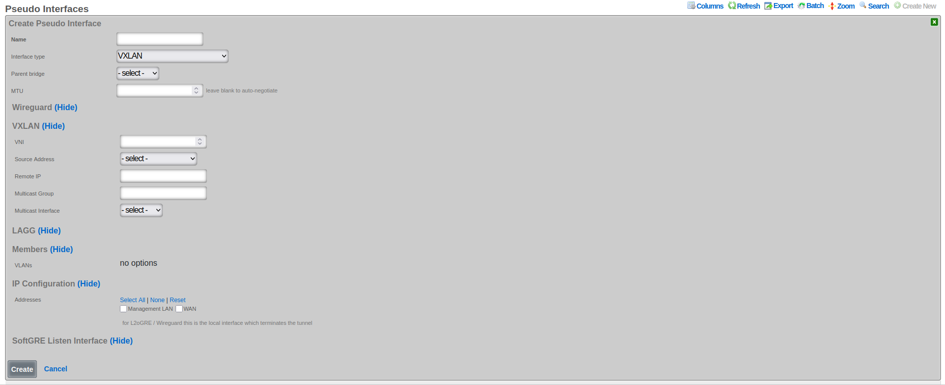
The following configuration steps provide guidance for configuring a VXLAN pseudo interface:
The Name field is an arbitrary string descriptor used only for administrative identification. Choose a name that reflects the purpose of the VXLAN segment, such as "Tenant-100-VXLAN" or "DataCenter-Overlay".
Set the Interface Type to VXLAN to enable VXLAN encapsulation and processing capabilities.
The Parent Bridge field enables hierarchical VXLAN configurations where this VXLAN becomes a child of a bridge.
Configure the MTU field to accommodate VXLAN encapsulation overhead. Subtract 50 bytes from the underlying network MTU (typically 1450 bytes for standard 1500-byte networks) to prevent fragmentation.
The VNI field (VXLAN Network Identifier) specifies the 24-bit value that uniquely identifies this VXLAN segment. This value must be coordinated across all VTEPs participating in the same overlay network. Valid range is 1 to 16,777,214.
The Source Address field specifies the source IP address used for VXLAN tunnel establishment. This address must be reachable from all remote VTEPs and should typically be assigned to a loopback or dedicated tunnel interface.
The Remote IP field contains comma-separated IP addresses of remote VTEPs when using unicast mode. Leave this field empty when using multicast group configuration.
The Multicast Group field specifies the multicast group address used for BUM (Broadcast, Unknown unicast, and Multicast) traffic distribution. Use addresses in the range 224.0.0.0 to 239.255.255.255, with organization-local scope (239.0.0.0/8) being preferred.
The VXLAN Device Interface field selects the underlying physical or logical interface through which VXLAN traffic transmits. This interface must support the required MTU size including VXLAN overhead.
Associate VLANs in the Members section to specify which VLAN traffic should be carried over this VXLAN tunnel. Only traffic from selected VLANs will be encapsulated and transmitted.
Assign Addresses in the IP Configuration section to enable IP communication over the VXLAN overlay. These addresses become available to devices connected through the VXLAN tunnel.
VXLAN Multicast Group Configuration
VXLAN multicast group configuration enables efficient distribution of broadcast, unknown unicast, and multicast (BUM) traffic across VXLAN segments. This approach leverages IP multicast infrastructure to eliminate the need for explicit peer configuration, simplifying deployment and improving scalability in large-scale VXLAN deployments.
When configuring a VXLAN interface with multicast support, operators specify a multicast group address that serves as the distribution tree root for BUM traffic. All VXLAN tunnel endpoints (VTEPs) participating in the same VXLAN segment join this multicast group, creating an automatic discovery mechanism that eliminates manual peer configuration. The multicast infrastructure handles group membership dynamically, automatically adjusting as VTEPs join or leave the network.
The multicast group address must fall within the designated multicast range (224.0.0.0 to 239.255.255.255) and should be chosen carefully to avoid conflicts with other multicast applications. Many organizations allocate specific multicast ranges for VXLAN use, ensuring systematic address assignment and preventing overlap. The Organization-Local Scope (239.0.0.0/8) often serves this purpose, as it provides adequate address space while remaining contained within the organization's network.
Multicast group configuration requires supporting infrastructure including multicast-enabled routers and switches throughout the underlay network. The Protocol Independent Multicast (PIM) protocol typically manages multicast routing, with PIM Sparse Mode (PIM-SM) being the most common deployment model. Operators must ensure that Rendezvous Points (RPs) are properly configured and that multicast routing tables correctly forward traffic between VTEPs.
VXLAN Remote IP vs Multicast Group Selection
The choice between unicast remote IP and multicast group configuration represents a fundamental architectural decision that affects scalability, complexity, and operational requirements. Each approach offers distinct advantages and trade-offs that operators must carefully consider based on their specific deployment requirements and infrastructure capabilities.
Unicast remote IP configuration provides explicit control over VXLAN tunnel endpoints by specifying exact peer addresses. This approach works in any IP network without requiring multicast support, making it suitable for deployments where multicast infrastructure is unavailable or undesirable. The explicit peer specification enhances security by limiting tunnel establishment to known endpoints and simplifies troubleshooting by creating clearly defined point-to-point relationships.
The unicast approach excels in small to medium deployments where the number of VTEPs remains manageable. Configuration remains straightforward, with each VTEP maintaining a list of peer addresses for tunnel establishment. This explicit configuration provides precise control over traffic flows and eliminates the complexity of multicast routing. However, scalability becomes challenging as the number of VTEPs grows, requiring full-mesh configuration that becomes increasingly difficult to manage.
Multicast group configuration offers superior scalability by eliminating the need for explicit peer configuration. VTEPs automatically discover peers through multicast group membership, enabling dynamic network growth without reconfiguration of existing nodes. This approach proves invaluable in large-scale deployments where hundreds or thousands of VTEPs must communicate. The automatic discovery mechanism also simplifies operations by eliminating manual configuration errors and reducing administrative overhead.
The selection between these approaches often depends on specific deployment constraints. Cloud environments frequently lack multicast support, making unicast configuration the only viable option. Enterprise data centers with modern infrastructure can leverage multicast for improved scalability. Hybrid approaches are also possible, where unicast handles known traffic flows while multicast manages BUM traffic distribution.
VXLAN MTU Configuration
Maximum Transmission Unit (MTU) configuration for VXLAN interfaces requires careful consideration of overhead introduced by encapsulation. VXLAN adds 50 bytes of overhead to each packet (8 bytes for VXLAN header, 8 bytes for UDP header, 20 bytes for IP header, and 14 bytes for Ethernet header), which must be accommodated within the underlay network MTU to prevent fragmentation and ensure optimal performance.
The overlay network MTU must be configured to account for VXLAN encapsulation overhead while ensuring that encapsulated packets do not exceed the underlay network's capabilities. In networks with standard 1500-byte MTU, the VXLAN interface MTU typically configures to 1450 bytes, leaving sufficient room for encapsulation headers. This conservative approach prevents fragmentation but may impact application performance that expects full 1500-byte payloads.
Jumbo frame support in the underlay network enables VXLAN interfaces to maintain standard 1500-byte MTU for overlay traffic. By configuring the underlay network with an MTU of 1550 bytes or larger, operators can accommodate VXLAN overhead without reducing the overlay MTU. Many modern data center networks support 9000-byte jumbo frames, providing ample headroom for various encapsulation types while maintaining standard MTUs for application traffic.
MTU configuration must remain consistent across all elements of the VXLAN infrastructure. This includes the VXLAN interfaces themselves, the underlying physical interfaces, and all intermediate network devices. Mismatched MTU configurations lead to silent packet drops that prove difficult to diagnose. The Path MTU Discovery (PMTUD) mechanism can help identify MTU constraints, but many networks disable ICMP messages required for PMTUD, necessitating careful manual configuration.
Bridge
The bridge interface allows two or more interfaces to have a connection between them at Layer 2. This essentially combines them into a single logical network segment, allowing devices connected to either interface to communicate directly with each other.
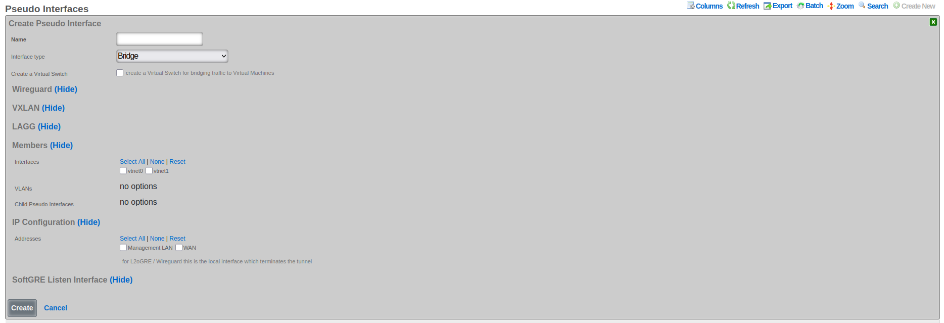
The following configuration steps provide guidance for configuring a Bridge pseudo interface:
- The Name field is an arbitrary string descriptor used only for administrative identification. Choose a descriptive name that indicates the bridge's purpose, such as "DataCenter-Core-Bridge" or "Campus-Aggregation".
- Set the Interface Type to Bridge to enable Layer 2 bridging capabilities across multiple interfaces.
- The Create Virtual Switch checkbox, when enabled, automatically provisions corresponding virtual switches in virtualization environments. This option appears only when virtualization hosts are configured and enables seamless integration between physical and virtual networks.
- In the Members section, select Child Pseudo Interfaces to specify which other pseudo interfaces (VXLAN, WireGuard, etc.) should be bridged together. Traffic flows freely between all selected child interfaces at Layer 2. Associate VLANs in the Members section to include specific VLAN interfaces in the bridge. Only selected VLAN traffic participates in the bridged network segment. Select Interfaces in the Members section to include physical ethernet interfaces in the bridge. This creates a direct Layer 2 connection between physical and virtual networks.
- Configure Addresses in the IP Configuration section to assign IP addresses to the bridge interface itself, enabling Layer 3 functionality such as routing and management access.
Bridge interfaces require careful consideration of MTU settings across all member interfaces. The system validates that all interfaces added to a bridge share the same MTU value to prevent frame size mismatches that could cause packet loss. When adding interfaces to an existing bridge, their MTU must match the bridge's configured MTU, ensuring consistent frame handling across the bridged segment.
The bridge implementation supports integration with virtual switch infrastructures when virtualization hosts are configured. This capability enables bridge interfaces to extend into virtualized environments, connecting physical and virtual networks seamlessly. The create virtual switch option automates the provisioning of corresponding virtual switches, simplifying deployment in virtualized infrastructures.
LAGG (Link Aggregation Group)
LAGG, which can also be referred to as LAG (Link Aggregation Group), stands for Link Aggregation. It's a networking technology that groups multiple physical network interfaces together into a single logical interface. This essentially combines the bandwidth and, in some cases, provides redundancy for network connections.
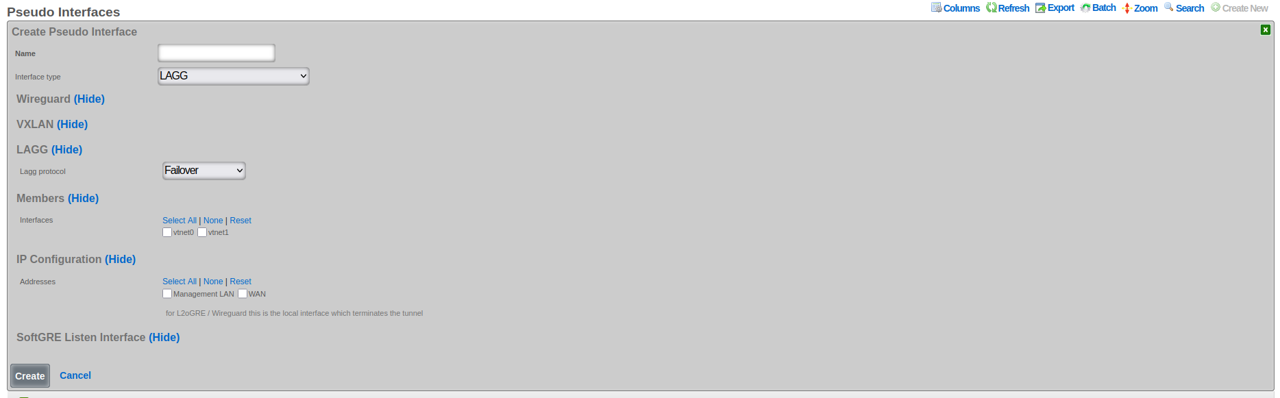
The following configuration steps provide guidance for configuring a LAGG pseudo interface:
The Name field is an arbitrary string descriptor used only for administrative identification. Choose a name that reflects the aggregation purpose, such as "Uplink-LAG" or "Server-Connection-AG".
Set the Interface Type to LAGG to enable link aggregation functionality.
The LAGG Protocol field determines the aggregation behavior and load distribution method:
- Failover: Designates one interface as primary with others as standby for redundancy
- Load Balance: Uses hash-based traffic distribution without requiring switch cooperation
- LACP: Implements IEEE 802.1AX for dynamic negotiation with compatible switches
- Round Robin: Distributes packets sequentially across all member interfaces
- Broadcast: Transmits each packet through all member interfaces simultaneously
In the Members section, select Interfaces to specify which physical or virtual Ethernet interfaces participate in the aggregation. All selected interfaces must have compatible speed and duplex settings.
Associate VLANs (if present in the given system) to enable tagged traffic across the aggregated link. VLAN configuration applies to the logical aggregated interface rather than individual member interfaces.
Configure Addresses in the IP configuration section to assign IP addresses to the aggregated interface. These addresses represent the logical interface and remain accessible even if individual member interfaces fail.
The rXg platform implements comprehensive LAGG support with multiple operational modes, each optimized for specific deployment requirements. The selection of LAGG protocol determines how traffic distributes across member interfaces and how the system responds to interface failures.
LAGG Failover Protocol Configuration
The failover protocol provides the simplest and most reliable form of link aggregation, designating one interface as primary and others as standby. This configuration ensures continuous connectivity by automatically switching to a standby interface when the primary fails, providing redundancy without the complexity of load distribution algorithms.
In failover mode, all traffic flows through the designated primary interface under normal conditions. The standby interfaces remain idle but continuously monitor their link status and maintain readiness for activation. When the primary interface fails, whether due to link loss, administrative action, or error threshold exceeded, the system immediately activates the highest-priority standby interface. This transition typically completes within milliseconds, minimizing service disruption.
The failover protocol supports multiple standby interfaces with configurable priority levels. Priority assignment determines the activation order when multiple standby interfaces are available. Higher priority interfaces activate first, with lower priority interfaces serving as additional backup options. This priority system enables sophisticated failover strategies where preferred paths activate in specific sequences based on performance characteristics or business requirements.
Configuration of failover protocol requires careful consideration of failure detection mechanisms. Link state monitoring provides the fastest detection for physical failures but cannot identify logical issues such as upstream connectivity problems. Advanced configurations can incorporate ping monitoring or BFD (Bidirectional Forwarding Detection) to verify end-to-end connectivity. These enhanced detection mechanisms ensure that failover occurs for both physical and logical failures, improving overall reliability.
LAGG LACP Setup and Requirements
Link Aggregation Control Protocol (LACP), defined in IEEE 802.1AX (formerly 802.3ad), provides dynamic negotiation and management of link aggregation groups. This protocol enables automatic configuration, continuous monitoring, and intelligent load distribution across multiple physical links, creating a robust and efficient aggregated interface.
LACP operates by exchanging control messages (LACPDUs) between participating devices to establish and maintain the aggregation. These messages carry information about system capabilities, port characteristics, and aggregation preferences. The protocol uses this information to automatically form aggregation groups, verify configuration consistency, and detect changes in the aggregation topology. This dynamic negotiation eliminates manual configuration errors and enables automatic adaptation to network changes.
The LACP configuration process begins with enabling the protocol on participating interfaces and configuring basic parameters. The system priority determines which device controls the aggregation when connected to another LACP-capable device. The port key identifies which ports can aggregate together, with ports sharing the same key eligible for aggregation. The aggregation mode, either active or passive, determines whether the port initiates LACP negotiation or waits for the peer to begin.
LACP requires compatible configuration on both ends of the aggregated link. The connected switch must support LACP and have matching configuration for successful aggregation. Key parameters that must align include the aggregation key, timeout values, and load distribution algorithm. Many switches default to passive LACP mode, requiring the rXg interface to operate in active mode to initiate negotiation. The timeout value, either short (1 second) or long (30 seconds), determines how quickly the system detects partner failures.
Load distribution in LACP aggregations uses hash-based algorithms to assign flows to specific member links. The hash calculation typically includes source and destination MAC addresses, IP addresses, and port numbers, ensuring that packets from the same flow follow the same path. This approach maintains packet ordering while distributing different flows across available links. The specific hash algorithm must be compatible between the rXg and connected switch for optimal distribution.
LAGG Load Balance, Round Robin, and Broadcast Modes
Beyond failover and LACP, LAGG interfaces support additional distribution modes that provide different traffic handling characteristics suited to specific deployment scenarios. These modes include load balance for hash-based distribution, round robin for sequential packet distribution, and broadcast for redundant transmission.
Load balance mode implements static hash-based distribution without the complexity of LACP negotiation. This mode proves valuable when connecting to devices that do not support LACP but can handle traffic from multiple source MAC addresses. The distribution algorithm uses a hash of packet headers to assign flows to specific member interfaces, maintaining packet order within flows while distributing load across available links. The hash calculation typically incorporates Layer 2, 3, and 4 headers, providing good distribution for diverse traffic patterns.
The load balance algorithm adapts to member interface changes by redistributing the hash space among remaining active interfaces. When an interface fails, its assigned flows redistribute to surviving interfaces. When an interface recovers, the algorithm gradually shifts flows to include the recovered interface, minimizing disruption to existing connections. This adaptive behavior provides both load distribution and redundancy without requiring protocol negotiation with connected devices.
Round robin mode provides the simplest distribution mechanism by sending each packet through the next available interface in sequence. This approach achieves near-perfect load distribution at the packet level, ensuring equal utilization of all member interfaces. However, round robin distribution can cause packet reordering when packets from the same flow traverse different paths with varying latencies. This reordering can significantly impact TCP performance and should be used only in controlled environments where reordering consequences are understood and acceptable.
Broadcast mode transmits every packet through all member interfaces simultaneously, creating redundant paths for critical traffic. This mode finds application in high-availability scenarios where packet loss must be minimized at the cost of increased bandwidth consumption. Industrial control systems and financial trading networks sometimes employ broadcast mode to ensure message delivery despite individual link failures. The receiving system must be capable of handling duplicate packets, either through explicit duplicate detection or by using protocols that naturally handle duplicates.
WireGuard
WireGuard is a modern, lightweight VPN protocol known for its simplicity, speed, and strong cryptography. It uses public key authentication and runs in the Linux/FreeBSD kernel for high performance, though it is also available on Windows, macOS, Android, and iOS. Configuration is minimal, often requiring just a few lines per peer. WireGuard establishes encrypted tunnels between devices, routing selected IP traffic securely. It is ideal for both personal VPNs and site-to-site secure networking.
The following configuration steps provide guidance for configuring a WireGuard pseudo interface:
The Name field is an arbitrary string descriptor used only for administrative identification. Choose a name that reflects the VPN's purpose, such as "Remote-Access-VPN" or "Site-to-Site-Tunnel".
Set the Interface Type to WireGuard to enable encrypted VPN tunnel capabilities.
The WG IP field specifies the IP address assigned to the WireGuard interface itself. This address becomes the tunnel endpoint and should be from a dedicated subnet used exclusively for WireGuard tunnels.
The WG Port field sets the UDP port number for WireGuard communication. The default port is 51820, but any available UDP port can be used. The system automatically selects unused ports when creating multiple WireGuard interfaces.
The WG Private Key field contains the cryptographic private key for this WireGuard interface. The system automatically generates secure keys when creating new interfaces. This key must be kept confidential and should be rotated periodically for security.
The WG Public Key field displays the corresponding public key derived from the private key. This public key is shared with peer devices to establish encrypted tunnels. The key updates automatically when the private key changes.
The Regenerate Keypair checkbox, when selected, generates new private and public keys for the interface. This action disconnects existing tunnels, requiring reconfiguration of all peer devices with the new public key.
Configure Network Addresses to assign additional IP ranges accessible through the WireGuard tunnel. These addresses enable routing to networks behind the WireGuard endpoint.
Associate the interface with IP Groups to apply policies, bandwidth limits, and access controls to WireGuard traffic. Different tunnels can be associated with different IP groups for granular policy enforcement.
There are at least three primary advantages of WireGuard compared to other VPN solutions:
Ease of use: WireGuard is designed to be simpler to set up and use compared to other VPN protocols like OpenVPN. This is achieved by having a lean codebase and focusing on essential functionalities.
High performance: WireGuard prioritizes speed. It uses modern cryptographic techniques and a streamlined approach to achieve faster connection speeds and lower latency compared to traditional VPN protocols.
Security: Despite its simplicity, WireGuard offers robust security. It utilizes state-of-the-art cryptography and keeps the attack surface minimal by design.
WireGuard Key Management
The rXg platform implements comprehensive key management for WireGuard interfaces, automating the generation and maintenance of cryptographic keys while providing flexibility for manual key configuration. Each WireGuard interface requires a unique private/public key pair that identifies the interface and enables secure tunnel establishment.
When creating a new WireGuard interface, the system automatically generates a cryptographically secure private key and derives the corresponding public key. This automatic generation uses the WireGuard toolset's native key generation functions, ensuring compatibility and security. The private key remains confidential and never leaves the rXg device, while the public key can be safely shared with peer devices for tunnel configuration.
The regenerate keypair functionality enables operators to rotate keys periodically or in response to security events. When triggered, the system generates a new key pair and updates the interface configuration. Existing tunnels using the old keys will disconnect and must be reconfigured with the new public key. This controlled key rotation maintains security while minimizing operational disruption.
Manual key configuration supports scenarios where specific keys must be used, such as when migrating from existing WireGuard deployments or integrating with external key management systems. Operators can provide a private key, and the system automatically derives and validates the corresponding public key. The system verifies key format and uniqueness to prevent configuration errors that could compromise security.
WireGuard Tunnel Configuration
WireGuard tunnels represent individual peer connections within a WireGuard interface. Each tunnel defines a remote peer that can communicate through the WireGuard interface, including the peer's public key, endpoint address, and allowed IP ranges. The rXg platform extends basic WireGuard tunnel functionality with advanced features for monitoring, policy enforcement, and traffic management.
Tunnel configuration begins with specifying the peer's public key, which uniquely identifies the remote endpoint and enables cryptographic verification. The endpoint address, consisting of an IP address and port number, tells the system where to send encrypted packets. For peers behind NAT or with dynamic addresses, the endpoint can be omitted, allowing the peer to initiate the connection.
The allowed IPs configuration defines which IP addresses can be routed through the tunnel. This setting serves dual purposes: it determines which traffic the local system sends through the tunnel and validates that received traffic originates from authorized addresses. The allowed IPs can range from specific host addresses (/32 for IPv4, /128 for IPv6) to entire networks, providing flexible routing control.
Persistent keepalive settings maintain tunnel connectivity through NAT devices and firewalls. When configured, the system sends periodic empty packets to keep NAT mappings active and ensure the tunnel remains reachable. The keepalive interval typically ranges from 25 to 60 seconds, balancing connectivity reliability with bandwidth consumption.
WireGuard IP Groups and Policies
The integration between WireGuard tunnels and IP groups enables sophisticated policy enforcement for VPN traffic. By associating tunnels with IP groups, operators can apply consistent security policies, bandwidth management, and access controls to VPN users, treating them identically to local network users.
IP group association occurs at the tunnel level, allowing different peers to receive different policy treatment even when connecting through the same WireGuard interface. This granular control enables multi-tenant VPN deployments where different user groups require distinct network access and service levels. The policy engine evaluates traffic from WireGuard tunnels using the same rules as local traffic, ensuring consistent security enforcement.
Bandwidth policies applied through IP groups enable fair resource allocation among VPN users. The system can enforce per-tunnel bandwidth limits, implement traffic shaping, and prioritize certain traffic types. These controls prevent individual VPN users from consuming excessive bandwidth while ensuring critical services receive adequate resources.
Access control policies restrict which network resources VPN users can access. By defining appropriate firewall rules within IP groups, operators can limit VPN users to specific servers, services, or network segments. Time-based policies enable different access levels during business hours versus off-hours, accommodating various usage patterns.
WireGuard Monitoring and Statistics
The rXg platform provides comprehensive monitoring capabilities for WireGuard interfaces and tunnels, enabling operators to track tunnel health, analyze traffic patterns, and troubleshoot connectivity issues. Real-time statistics and historical data provide insights into VPN usage and performance.
Handshake monitoring tracks the cryptographic handshake status for each tunnel. The last handshake timestamp indicates when the tunnel last successfully authenticated, helping identify inactive or problematic connections. Tunnels without recent handshakes may indicate configuration errors, network connectivity issues, or inactive peers.
Traffic statistics track bytes transmitted and received for each tunnel, providing visibility into bandwidth consumption and usage patterns. These counters enable capacity planning, usage-based billing, and identification of abnormal traffic patterns. The system maintains both current counters and historical data, enabling trend analysis and reporting.
Ping target integration enables active monitoring of tunnel connectivity. By configuring ping targets for WireGuard tunnels, the system continuously verifies end-to-end connectivity through the VPN. Failed ping targets can trigger alerts, initiate failover actions, or adjust routing decisions, ensuring reliable VPN connectivity.
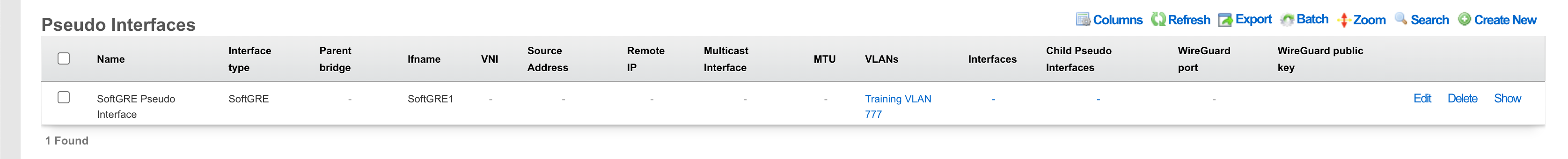
SoftGRE
A SoftGRE tunnel is a type of tunneling protocol that uses Generic Routing Encapsulation (GRE, see RFC 2784) to transport Layer 2 Ethernet traffic over an IP network. In simpler terms, it encapsulates Ethernet data packets (overlay traffic) within GRE IP packets, allowing them to be sent across an IP network (underlay network) that would not otherwise support them.
The terms "overlay" and "underlay" describe the layers in a GRE tunnel setup. The underlay network refers to the physical or IP infrastructure that carries packetssuch as routers and links across the internet. The overlay network is the virtual network created by the GRE tunnel, allowing devices to communicate as if they're on the same local network, regardless of physical location. The GRE tunnel encapsulates overlay traffic within underlay packets, enabling features like layer 2 discovery across separate physical sites. This separation allows more flexible and scalable network designs while relying on the underlay for actual packet delivery.
The softGRE daemon supports both IPv4 and IPv6 underlay networks. The softGRE daemon supports both IPv4 and IPv6 overlay traffic. Any combination of underlay and overlay IP protocols is supported.
SoftGRE tunnels are particularly useful for extending Wi-Fi networks. Such L2 tunnels can be used to connect geographically separated Wi-Fi access points (APs) to a central rXg, creating a seamless network for users.
The following configuration steps provide an example of how to configure the rXg as an endpoint for a SoftGRE tunnel.
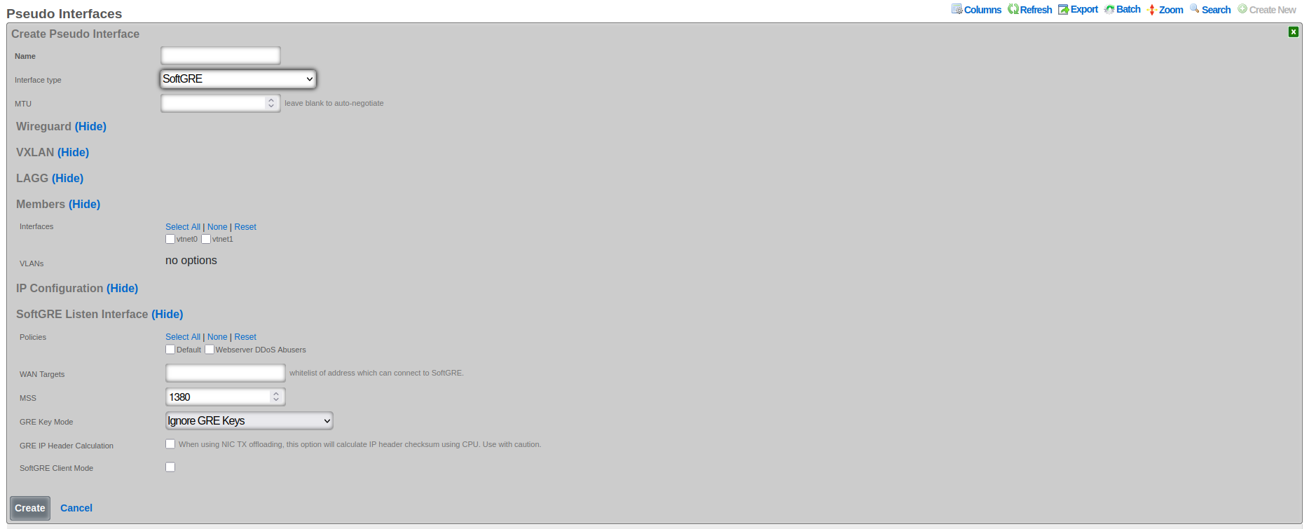
- The name field is an arbitrary string descriptor used only for administrative identification. Choose a name that reflects the purpose of the record. This field has no bearing on the configuration or settings determined by this scaffold.
- Set the Interface type to SoftGRE.
- The Members field indicates where tunneled traffic can egress. Interfaces can be used for untagged traffic and VLANs will be used for tagged traffic.
**NOTE* that the softGRE daemon monitors traffic on all LAN and WAN interfaces, including tagged and untagged interfaces, on the rXg platform and the selection of specific interfaces / VLANs in the Members section influences only the traffic egress, not the ingress.*
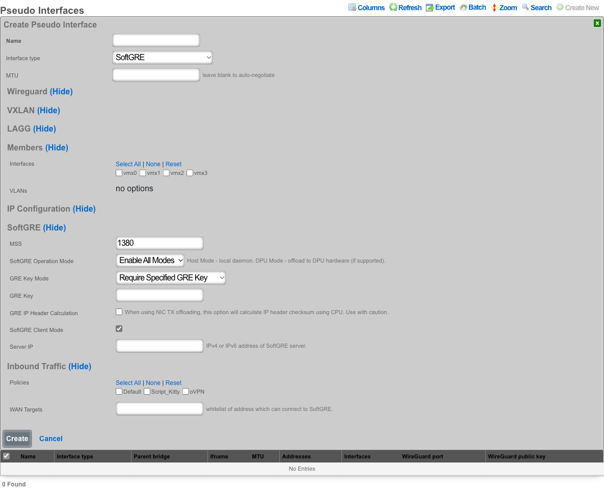
In the SoftGRE section, configure the tunnel behavior:
- MSS sets the Maximum Segment Size for TCP connections through the tunnel (default 1380).
- SoftGRE Operation Mode controls where the tunnel is processed: Enable All Modes runs on both host and DPU, Host Mode runs on the host CPU only, and DPU Mode offloads to DPU hardware (requires a compatible DPU device).
- GRE Key Mode, GRE IP Header Calculation, SoftGRE Client Mode, and Server IP are described in the advanced features sections below.
In the Inbound Traffic section you have an option to restrict where the incoming SoftGRE connections are accepted from. Policies are used to identify LAN side tunnels and WAN Targets are used to identify tunnels originating from the WAN. By default, all LAN and WAN interfaces are monitored by the softGRE daemon.
For vendor-specific configuration examples and additional SoftGRE configuration details, see the Miscellaneous SoftGRE Documentation.
SoftGRE Advanced Features
GRE Key Modes and Traffic Segregation
GRE key functionality provides critical traffic segregation and security capabilities for SoftGRE tunnels. The key field in the GRE header enables multiple logical tunnels to share the same source and destination IP addresses while maintaining traffic isolation. The rXg platform implements comprehensive key handling modes that accommodate various deployment scenarios and security requirements.
The Ignore GRE Keys mode treats all incoming traffic identically regardless of GRE key presence or value. This permissive approach simplifies configuration when traffic segregation is handled through other mechanisms such as VLAN tagging or IP addressing. This mode proves useful during migration scenarios where some endpoints include keys while others do not, allowing gradual transition without service disruption.
The Reject GRE Key Packets mode enforces strict security by dropping any packets that contain a GRE key. This configuration ensures that only keyless GRE packets enter the tunnel, preventing unauthorized traffic injection from endpoints that might attempt to use keys for bypassing security controls. Organizations requiring strict traffic validation often employ reject mode to ensure that all traffic follows expected patterns without unexpected key-based routing.
The Require Specified GRE Key mode mandates that all packets must contain a specific GRE key value for acceptance. This strict enforcement creates authenticated tunnels where only endpoints possessing the correct key can inject traffic. The key effectively serves as a shared secret, providing basic authentication without the overhead of cryptographic operations. Multiple tunnels can terminate on the same IP addresses by using different required keys, enabling efficient address utilization while maintaining complete traffic isolation.
VLAN-to-Key Mapping Modes
Advanced GRE key modes enable sophisticated mapping between VLAN IDs and GRE keys, automating traffic segregation in complex multi-tenant environments. These mapping modes eliminate manual key configuration by deriving key values from VLAN tags, ensuring consistent traffic isolation across the overlay network.
The Use GRE Key to Assign VLAN mode creates a direct correspondence between GRE keys and VLAN IDs, where the key value equals the VLAN ID. This straightforward mapping simplifies troubleshooting and ensures intuitive traffic flow visualization. When a packet arrives with VLAN tag 100, the system automatically applies GRE key 100 during encapsulation. Similarly, received packets with GRE key 100 map to VLAN 100 upon decapsulation. This bidirectional mapping maintains VLAN segregation across the GRE overlay without requiring explicit configuration for each VLAN.
The Prefer GRE Key over VLAN mode implements a flexible hierarchy where GRE keys take precedence when present, but VLAN-based mapping provides a fallback mechanism. If an incoming packet includes a GRE key, the system uses that key value for traffic handling. When no key is present, the system examines VLAN tags and applies corresponding mapping rules. This mode accommodates mixed environments where some traffic sources support GRE keys while others rely solely on VLAN tagging.
The Prefer VLAN over GRE Key mode reverses the precedence, prioritizing VLAN-based mapping while accepting GRE keys as an alternative. This configuration proves valuable when VLAN tags represent the primary segregation mechanism, but some traffic sources can only provide GRE keys. The system first attempts VLAN-based mapping, falling back to GRE key interpretation when no VLAN tag exists. This approach maintains consistency with VLAN-centric network designs while accommodating key-based traffic sources.
IP Header Calculation and Checksum Handling
The IP header calculation option addresses compatibility issues between GRE encapsulation and network interface checksum offloading. Modern network interfaces often defer checksum calculation to hardware, improving CPU efficiency. However, this optimization can create problems when packets undergo GRE encapsulation before hardware checksum calculation occurs.
When checksum offloading is enabled on the underlying interface, packets enter the GRE tunnel with zero-value checksums, expecting hardware to calculate the correct values during transmission. However, GRE encapsulation occurs in software before packets reach the hardware, resulting in encapsulated packets containing invalid inner checksums. The receiving endpoint cannot verify packet integrity, leading to drops or corruption.
The GRE IP Header Calculation option forces software-based checksum computation before GRE encapsulation, ensuring that encapsulated packets contain valid checksums regardless of hardware offloading configuration. This software calculation incurs additional CPU overhead but guarantees compatibility across diverse hardware configurations. The option proves essential when the underlying network includes interfaces with varying offload capabilities or when hardware offload behavior cannot be controlled.
Enabling IP header calculation involves performance trade-offs that operators must carefully consider. Software checksum calculation increases CPU utilization, potentially limiting tunnel throughput on systems with limited processing resources. However, the compatibility benefits often outweigh performance impacts, especially in heterogeneous environments where hardware capabilities vary. The system provides detailed statistics on checksum calculation overhead, enabling operators to assess the performance impact and make informed configuration decisions.
Client/Server Mode Operation
When enabled, the SoftGRE Client Mode transforms the SoftGRE interface from a passive tunnel endpoint into an active initiator that establishes connections to remote GRE servers. This operational mode proves invaluable for scenarios where the rXg device operates behind NAT or requires explicit connection establishment to traverse firewalls.
In client mode, the SoftGRE interface initiates tunnel establishment by sending keepalive packets to the configured server IP address. These keepalives serve multiple purposes including initial tunnel establishment, NAT traversal through regular traffic generation, and continuous liveness detection. The server endpoint learns the client's public IP address from received packets, automatically adapting to address changes that occur due to DHCP renewal or failover events.
The client mode configuration requires specification of the server IP address, which represents the remote endpoint's stable public address. This server must be reachable from the client's network and capable of accepting GRE traffic. The client automatically handles NAT traversal by ensuring that outbound packets create the necessary NAT mappings for return traffic. This automatic NAT handling eliminates complex manual configuration and enables deployment in diverse network environments.
Client mode includes intelligent reconnection logic that handles various failure scenarios. If the tunnel loses connectivity, the client automatically attempts reconnection using exponential backoff to prevent overwhelming the server. The system monitors tunnel statistics and adjusts keepalive intervals based on observed stability, reducing overhead on stable connections while maintaining quick detection of failures.
Server configuration in SoftGRE establishes the endpoint address for client-mode tunnels, creating a stable target for incoming connections. The server IP address must be publicly reachable and stable, as clients rely on this address for tunnel establishment. Static IP addresses work best, though dynamic DNS can accommodate scenarios where the server address occasionally changes. The server interface must be configured to accept incoming GRE traffic, which may require firewall adjustments to permit protocol 47 (GRE) from client networks.
MTU and MSS Configuration
Proper MTU and MSS configuration ensures optimal performance while preventing fragmentation in GRE tunnels. The encapsulation overhead introduced by GRE headers reduces the effective payload capacity, requiring careful calculation to maintain efficient packet transmission without triggering fragmentation.
The GRE encapsulation adds 24 bytes of overhead in the standard configuration, consisting of 4 bytes for the GRE header and 20 bytes for the outer IP header. When VLAN tags are present, each tag adds 4 additional bytes. The total overhead must be subtracted from the underlying network MTU to determine the maximum payload size that can traverse the tunnel without fragmentation. For example, with a standard 1500-byte network MTU and single VLAN tag on both inner and outer packets, the effective payload MTU becomes 1468 bytes (1500 - 24 - 4 - 4).
Maximum Segment Size (MSS) configuration for TCP connections requires additional consideration beyond basic MTU calculations. MSS represents the largest TCP payload that can be transmitted without fragmentation, which equals the MTU minus IP and TCP header overhead. For IPv4, this means subtracting an additional 40 bytes (20 for IP, 20 for TCP) from the tunnel MTU. The system can automatically adjust TCP MSS values through MSS clamping, ensuring that connections use appropriate segment sizes regardless of endpoint configuration.
The platform enforces MSS boundaries to prevent configuration errors that could impact performance or stability. The minimum MSS of 576 bytes ensures compatibility with all IP implementations, as this represents the minimum reassembly buffer size required by IPv4 specifications. The maximum MSS cannot exceed the calculated tunnel capacity based on underlying MTU and encapsulation overhead. These validations prevent misconfigurations that could lead to excessive fragmentation or packet loss.
WAN Targets and Policies Configuration
WAN targets and policies configuration controls which external networks can establish GRE tunnels to the rXg device, implementing security boundaries and traffic segregation. This configuration proves essential for deployments where tunnels originate from untrusted networks or where different tunnel sources require different handling.
WAN targets define specific external endpoints authorized to establish tunnels. Each target specifies an IP address or range from which GRE traffic will be accepted. This explicit allowlisting ensures that only known and authorized endpoints can inject traffic into the overlay network. Targets can be static addresses for fixed endpoints or dynamic ranges for scenarios where clients obtain addresses through DHCP. The system continuously validates incoming traffic against configured targets, dropping packets from unauthorized sources.
Policy associations provide sophisticated traffic handling based on tunnel source characteristics. Different policies can apply to tunnels from different WAN targets, enabling differentiated services, security controls, and routing decisions. For example, tunnels from branch offices might receive different QoS treatment than those from partner networks. Policies can enforce bandwidth limits, apply security filters, or direct traffic to specific network segments based on the tunnel source.
The combination of WAN targets and policies enables complex multi-tenant scenarios where a single rXg device serves multiple independent networks. Each tenant's tunnels terminate on the same physical interface but receive completely isolated treatment through policy separation. This approach maximizes hardware utilization while maintaining strict security boundaries between different traffic sources.
VPP (Vector Packet Processing) Interfaces
Introduction to VPP Interfaces
Vector Packet Processing represents a revolutionary approach to packet processing that achieves exceptional performance through batch processing and CPU cache optimization. VPP interfaces on the rXg platform leverage this technology to deliver line-rate packet processing capabilities that far exceed traditional kernel-based networking stacks. These interfaces provide hardware-accelerated networking functions while maintaining the flexibility and programmability required for modern network services.
The VPP architecture processes packets in vectors (batches) rather than individually, amortizing processing overhead across multiple packets and maximizing CPU cache utilization. This approach enables VPP interfaces to handle millions of packets per second on standard server hardware, with even higher performance when combined with specialized acceleration hardware. The processing pipeline remains fully programmable, allowing dynamic insertion of features such as ACLs, NAT, and tunnel termination without requiring kernel modifications.
VPP interfaces operate in a dedicated userspace environment, bypassing the kernel networking stack entirely. This design eliminates context switching overhead and provides deterministic performance characteristics essential for latency-sensitive applications. The interfaces maintain compatibility with standard networking protocols and management interfaces while delivering performance improvements of 10x or more compared to traditional approaches.
DPU Device Integration and Hardware Acceleration
Data Processing Units (DPUs) represent specialized processors designed specifically for network and storage workloads. The integration between VPP interfaces and DPU devices on the rXg platform creates a powerful hardware-accelerated networking solution that offloads complex packet processing tasks from the main CPU while maintaining full programmability and flexibility.
DPU integration occurs transparently when VPP interfaces detect compatible hardware. The system automatically identifies available DPU devices during initialization and establishes communication channels between the VPP framework and DPU processors. This integration includes firmware version verification, capability negotiation, and resource allocation to ensure optimal utilization of available hardware acceleration features.
The DPU handles computationally intensive operations that would otherwise consume significant CPU resources. These operations include cryptographic functions for VPN termination, pattern matching for deep packet inspection, and complex header manipulations for tunnel processing. By offloading these tasks to dedicated hardware, the main CPU remains available for control plane operations and application workloads, improving overall system performance and efficiency.
Hardware acceleration through DPU devices extends beyond simple offload capabilities. The DPU can implement complete network functions such as load balancing, firewall processing, and traffic shaping entirely in hardware. These hardware-implemented functions operate at line rate regardless of packet size or complexity, providing consistent and predictable performance. The tight integration between VPP and DPU ensures that hardware-accelerated functions seamlessly integrate with software-based features, creating a unified and flexible networking platform.
The management interface provides comprehensive visibility into DPU utilization and performance. Operators can monitor hardware resource consumption, track offload effectiveness, and identify potential bottlenecks. The system includes automatic failover capabilities that redirect processing to software paths if hardware resources become unavailable, ensuring continuous operation even during hardware maintenance or failure scenarios.
VPP interfaces are automatically created and managed by the system when DPU devices are detected and configured. The following steps describe how to identify and monitor VPP interfaces:
Automatic Interface Detection: VPP interfaces appear automatically in the pseudo interface list when compatible DPU hardware is detected. Interface names follow the pattern "dpu0", "dpu1", etc., corresponding to detected DPU devices.
Interface Status Monitoring: Check the Status field to verify that VPP interfaces are operational. Active interfaces show "UP" status, while inactive interfaces may indicate hardware issues or configuration problems.
Hardware Resource Monitoring: View the DPU Utilization metrics to track hardware acceleration effectiveness. High utilization may indicate the need for additional DPU resources or traffic optimization.
Performance Statistics: Monitor Packets Per Second and Bytes Transmitted/Received counters to assess VPP interface performance. These metrics help identify bottlenecks and validate hardware acceleration benefits.
Address Assignment: Network Addresses can be assigned to VPP interfaces for management and routing purposes, similar to other pseudo interfaces. These addresses enable direct communication with the VPP interface.
Policy Association: VPP interfaces support IP Group associations for applying security policies, bandwidth limits, and access controls to hardware-accelerated traffic.
Failover Monitoring: The system automatically monitors hardware health and redirects traffic to software processing if DPU devices become unavailable. Check the Failover Status to verify backup processing capability.
Automated Configuration Workflow
The DPU configuration workflow operates entirely automatically, requiring no manual intervention once compatible hardware is detected. This automation ensures optimal performance while eliminating configuration errors that could impact system stability. These interfaces cannot be manually created through the scaffold interface, as they require specific hardware resources and automatic configuration based on the DPU device capabilities. The system assigns unique interface names to VPP interfaces based on the associated DPU device, ensuring clear identification and management.
DPU Detection and Configuration Flow:

  1. Hardware Detection Phase
      PCIe bus enumeration
      DPU device identification
      Firmware version verification

  2. Resource Allocation
      Memory pool assignment
      CPU core affinity configuration
      Network queue mapping

  3. VPP Interface Creation
      Interface naming (dpu0, dpu1, etc.)
      Hardware offload capability negotiation
      Feature pipeline configuration

  4. Integration with rXg Framework
      Address assignment
      Policy association
      Monitoring infrastructure setup
Phase 1: Discovery and Enumeration During system initialization, the rXg platform scans the PCIe bus to identify connected DPU devices. The discovery process examines device IDs, vendor information, and capability registers to determine device type and supported features. Each discovered DPU undergoes firmware version verification to ensure compatibility with the current rXg release.
Phase 2: Resource Planning and Allocation The system analyzes available system resources and DPU capabilities to determine optimal resource allocation strategies. This includes memory pool sizing, interrupt vector assignment, and CPU core affinity optimization. The allocation process considers both performance requirements and system stability constraints.
Phase 3: VPP Framework Integration Compatible DPUs integrate directly with the VPP packet processing framework, creating high-performance data plane instances. The integration process establishes shared memory regions, configures interrupt handling, and initializes hardware acceleration features. Each DPU receives a unique interface identifier that enables management and monitoring through standard rXg interfaces.
Phase 4: Feature Enablement and Optimization The final configuration phase enables advanced features based on DPU capabilities and system requirements. This includes cryptographic acceleration, pattern matching engines, and quality of service mechanisms. The system performs automatic performance tuning based on observed traffic patterns and hardware characteristics.
Configuration Examples
Single DPU Deployment
System Configuration:

  Physical Server
   CPU: Intel Xeon (Management)
   Memory: 64GB System RAM
   DPU: BlueField-2 (25Gbps)
      Interface: dpu0
      Offload: Crypto, ACL, NAT
      Memory: 16GB dedicated
   Network: 2x25G + 1x1G management


Automatic Interface Creation:
 dpu0: Primary data plane interface
 dpu0_mgmt: Management interface
 dpu0_rep: Representor for host communication
Dual DPU High Availability
System Configuration:

  High-Performance Server
   CPU: Intel Xeon Gold (Management)
   Memory: 128GB System RAM
   DPU0: BlueField-3 (100Gbps)
      Interfaces: dpu0, dpu0_backup
      Role: Primary packet processing
   DPU1: BlueField-3 (100Gbps)
      Interfaces: dpu1, dpu1_backup
      Role: Standby/Load sharing
   Network: 4x100G + 2x10G management


Failover Configuration:
 Primary: dpu0 handles all traffic
 Standby: dpu1 monitors and ready for takeover
 Automatic failover in <100ms
 Stateful connection preservation
Monitoring and Management
DPU interfaces provide comprehensive monitoring capabilities that integrate seamlessly with the rXg management framework. Operators can monitor hardware utilization, offload effectiveness, and performance metrics through standard interfaces.
The system tracks key performance indicators including packet processing rates, hardware acceleration utilization, memory consumption, and error conditions. These metrics enable capacity planning, performance optimization, and proactive issue identification. Advanced monitoring features include per-flow statistics, latency measurements, and quality of service compliance tracking.
Administrative functions support firmware updates, configuration changes, and diagnostic operations. The system provides safe update mechanisms that maintain service continuity during maintenance operations. Configuration changes propagate automatically to affected DPU instances, ensuring consistent behavior across the entire system.
DPU Variants
The rXg platform supports multiple DPU variants, each optimized for specific networking workloads and performance requirements. The system automatically detects and configures supported DPU devices during initialization, creating appropriate VPP interfaces and establishing hardware acceleration paths.
BlueField-2 DPU Series
The NVIDIA BlueField-2 family represents high-performance DPUs designed for data center and cloud networking applications. These devices integrate ARM processors with advanced networking acceleration capabilities, supporting line-rate packet processing at 25/100/200 Gbps speeds. The BlueField-2 DPUs excel at cryptographic operations, deep packet inspection, and complex header processing tasks.
BlueField-3 DPU Series
The next-generation BlueField-3 DPUs provide enhanced performance and expanded feature sets compared to their predecessors. These devices support higher throughput rates, additional cryptographic algorithms, and improved programmability through enhanced SDK support. BlueField-3 DPUs integrate seamlessly with container orchestration platforms and provide hardware-accelerated service mesh functionality.
Intel Infrastructure Processing Unit (IPU)
Intel IPUs focus on infrastructure acceleration and workload isolation capabilities. These devices excel at providing consistent performance for network functions while maintaining strong security boundaries between different workloads. Intel IPUs support advanced traffic management features and provide hardware-accelerated load balancing capabilities. At this time the support for IPUs is at the R&D phase.
VLANs

The rXg defines a logical 802.1Q virtual LAN interface for each entry in the VLANs scaffold. A good reference for understanding VLANs and trunk ports is Network Warrior (ISBN 0596101511) by Gary Donahue.
Creating a VLAN implies that the Ethernet interface that is directly associated with it is a VLAN trunk port. The device connected to the Ethernet interface must be similarly configured to accept traffic for the VLAN ID specified in this record.
The Physical Interface drop down associates this VLAN logical interface with an Ethernet interface. A VLAN logical interface presents itself in the same manner as a Ethernet interface for network address configuration and policy management purposes. However, the VLAN must be associated with an Ethernet interface so that it knows what physical port to transmit and receive on.
The Service VLAN drop down associates this VLAN with a Q-in-Q parent VLAN interface. Note: if using Q-in-Q the operator should make sure that VLAN hardware filtering is disabled on the Ethernet Interface by navigating to Network::LAN editing the interface and confirm that the VLAN hardware filtering box is unchecked.
The name field is an arbitrary string descriptor used only for administrative identification. Choose a name that reflects the purpose of the record. This field has no bearing on the configuration or settings determined by this scaffold.
The VLAN ID is an integer value that is used in the VLAN identifier field of the frames transferred over the physical interface defined by this record. The field is 12-bits in the ethernet frame, making the range of values from 0 to 4096. The 0 value is reserved for native traffic and 1 is used for management by many bridges and switches. In addition, 4095 is reserved by most implementations.
The I-SIDs (Backbone Service Instance Identifier) can be used to identify any virtualized traffic across an 802.1ah encapsulated frame.
The Autoincrement drop down changes how VLANs are configured with regards to the number of subnets. none | single L2 | n tags=1 will result in a single VLAN being associated to a single subnet or subnets. per-subnet | auto-increment L2 w/L3 | n tags = subnets / ratio means the number of VLANs that will be configured is the number of Subnets divided by the ration. With a Ratio of 1 and tied to a Network Address that has 32 subnets, 32 VLANs will be configured. With a Ratio of 2 and a Network Address with 32 subnets, 16 VLANs will be configured (32 / 2 = 16).per-IP | auto-increment L2 over split L3 via BNG | n tags = (usable IPs / ratio)means if we have a Network Address configured with 32 usable IP addresses the number of VLANs that will be configured is the number of IP address divided by the ratio. Given a Network Address with 32 usable IP addresses and a Ratio of 1, 32 VLANs will be configured. If the Ratio is set to 2, 16 VLANs will be configured (32 / 2 = 16).
The Ratio field is the number of autoincrement subnets or usable IPs in each VLAN tag.
The MAC Override allows the operator to adjust the MAC address(es) assigned to each VLAN interface created based on this VLAN configuration. The MAC address assigned to each VLAN will be the MAC Override incremented for each VLAN interface created. The first VLAN interface created will use the value of MAC Override. For each additional VLAN created, the value will be incremented by 1. For example a MAC Override of ff:ff:fe:00:00:1a with a vlan tag of 10 will result in a MAC address of ff:ff:fe:00:00:1a being assigned to the vlan10 interface. When using autoincrement, vlan11 will be assigned ff:ff:fe:00:00:1b , vlan12 will be assigned ff:ff:fe:00:00:1c , etc.
The addresses field associates one or more network addresses with this VLAN logical interface. All interfaces, including logical VLAN interfaces, must have one or more network addresses associated with them in order for them to pass traffic.
The Switch Port Profiles field allows the operator to associate the VLAN(s) to a switch port profile that will automatically configured the VLAN(s) to the switch ports attached to the profile.
The WLANs field allows the operator to associate the VLAN(s) to a WLAN.
The Conference options field allows the operator to associate the VLAN(s) to a conference record so the VLAN(s) can be used when created a conference via the Conference Tool.
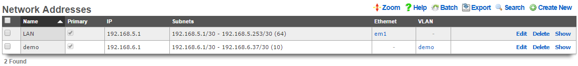
Network Addresses
An entry in the network addresses scaffold defines an IP block that will be associated with an interface, uplink or VLAN.
The name field is an arbitrary string descriptor used only for administrative identification. Choose a name that reflects the purpose of the record. This field has no bearing on the configuration or settings determined by this scaffold.
The IP field specifies the IP address using CIDR notation that will be configured on the interface specified. If the address record will be used for configuring multiple addresses on the interface via the span field, the IP field configures the first (lowest) IP address of the range.
The span field specifies the range of IP addresses configured by this address record. The default value of 1 is assumed if this field is omitted. For LAN links, a span of 1 is typical. For WAN links, a span of greater than 1 automatically enables translation pooling in NAT scenarios. In addition, bidirectional network address translation (BiNAT) requires the WAN link to span one additional address for each BiNAT.
Examples using Autoincrement
1. Autoincrement with 1:1 VLAN per subnet (MDU)
In this example the VLAN is configured per-subnet with a ratio of 1, this means that each subnet will have it's own VLAN tag. The number of VLANs used will be the number of subnets divied by the ratio. For this example there will be 128 /24 subnets tied to the VLAN which will result in 128 VLANs.
Create a new VLAN Interface , give it a name, select the Physical Interface the VLANs will be tied to. Set the VLAN IDs field to first VLAN to be used. Autoincrement is set to per-subnet , and Ratio is set to 1. If the Network Address is created already it can be selected, in this case it does not, click Create.
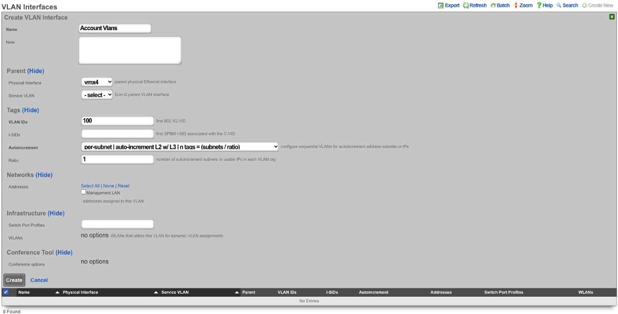

Next create a new Network Address , give it a name. Under the Interface section set the Ethernet field to select, and the VLAN field to the VLAN created in the previous step. Set the IP field to the desired starting network address using CIDR notation. Next set the Autoincrement field to the desired number of subnets to create, in this case it will be set to 128. Check the Create DHCP Pool box and then click Create.
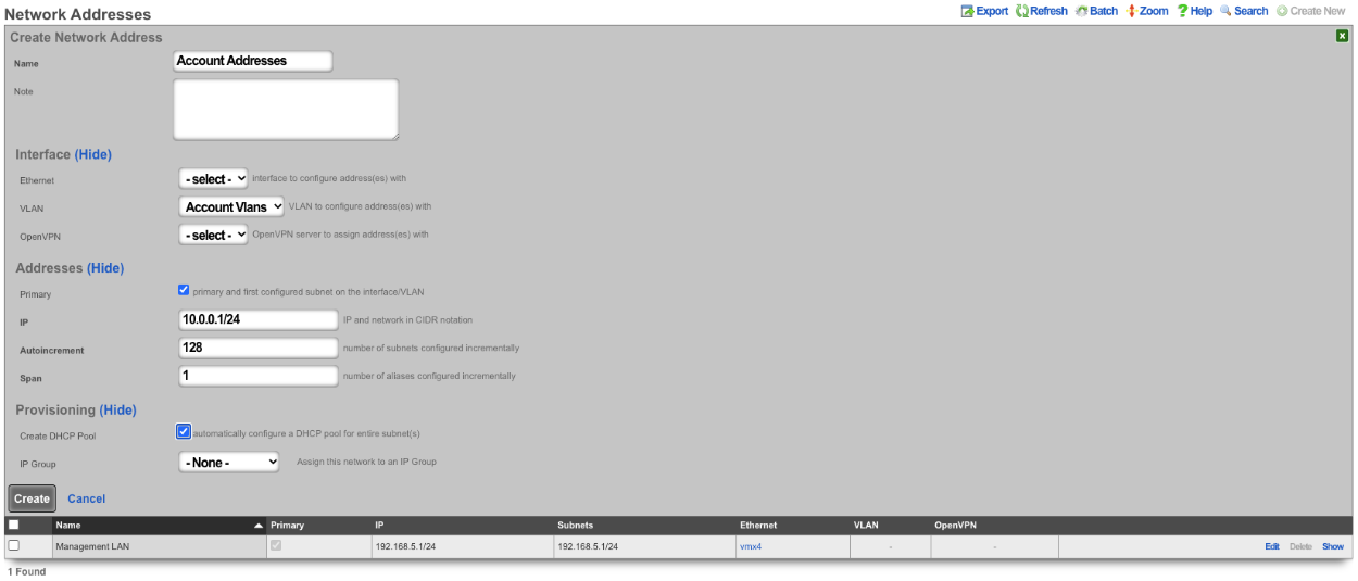
Now there are 128 /24 subnets that have been created (10.0.0.1/24-10.0.127.1/24), and 128 VLANs have been configured (100-227) tied sequentially to the subnets.
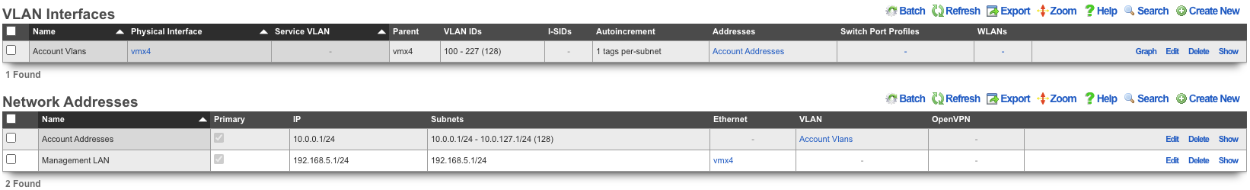
2. Autoincrement with more than 1 subnet per VLAN
In this example the configuration will put more than 1 subnet into each VLAN. The number of VLANs in this case will be the number of subnets divided by the ratio. In this example there are 64 /30 subnets and the ratio will be set to 4. In this configuration there will end up being 16 VLANs configured.
Create a new VLAN Interface , give it a name, select the Physical Interface the VLANs will be tied to. Set the VLAN ID's field to the first VLAN to be used. Autoincrement is set to per-subnet , and Ratio is set to 4. If the Network Address is created already it can be selected, in this case it does not, click Create.
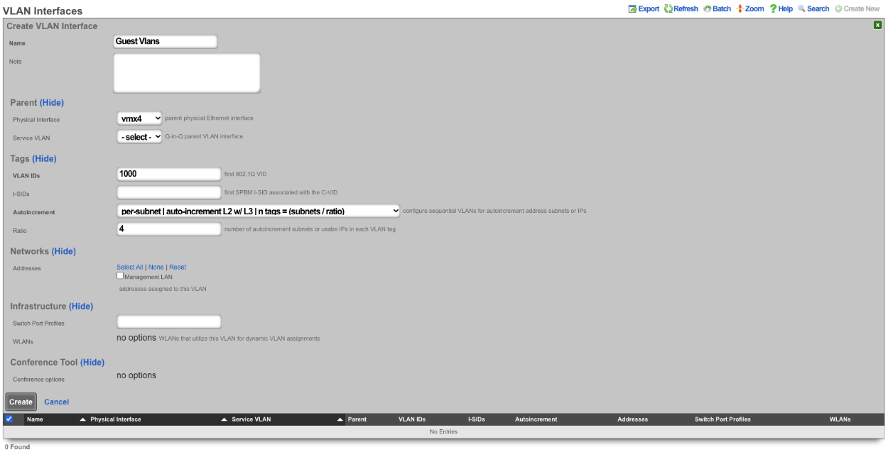

Next create a new Network Address , give it a name. Under the Interface section set the Ethernet field to select, and the VLAN field to the VLAN created in the previous step. Set the IP field to the desired starting network address using CIDR notation. Next set the Autoincrement field to the desired number of subnets to create, in this case it will be set to 64. Check the Create DHCP Pool box and then click Create
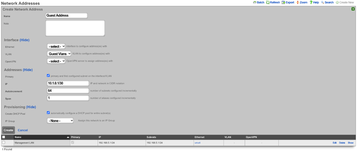
With this configuration there are 64 /30 subnets with 4 subnets per VLAN. 64(subnets) / 4(Ratio) gives us a total of 16 VLANs.
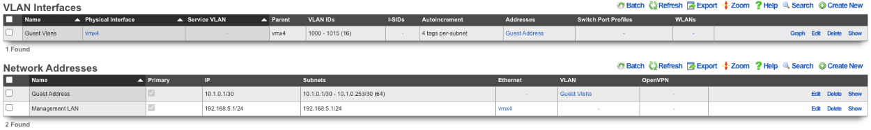
3. BNG with many VLANS inside a single subnet.
The autoincrement BNG feature enables a single subnet to be divided amongst a large number of VLANs. Autoincrement BNG maximizes public address space distribution efficiency. A public /24 CIDR block would typically need to be divided into 64 /30 CIDRs for distribution amongst subscribers. Each of the /30 CIDRs would then be assigned to a unique layer 2 microsegment. Thus a /24 CIDR block would typically support 64 subcscribers. This is an inefficient use of public IPv4 address space.
| Network | VLAN |
|---|---|
| 76.77.78.0/30 | VLAN 1000 |
| 76.77.78.4/30 | VLAN 1001 |
| 76.77.78.8/30 | VLAN 1002 |
| ⋮ | ⋮ |
| 76.77.78.248/30 | VLAN 1062 |
| 76.77.78.252/30 | VLAN 1063 |
The autoincrement BNG feature enables efficient distribution of public static IPv4 24 CIDR blocks. For example, a /24 CIDR block can support 253 subscribers where each subscriber is microsegmented onto their own unique layer two on the distribution infrastructure. It may help to think of this as autoincrementing VLAN assignment via /32s instead of /30s. The difference is that all of the /32s share a single gateway that is accessible from all VLANs. In reality the BNG autoincrement mechanism enables distribution of the addresses on a /24 subnet to ensure client compatibility. This enables efficient use of address space while enforcing true segmentation through a universally compatible standards-based approach.
| Network | VLAN |
|---|---|
| 76.77.78.2/24 | VLAN 1000 |
| 76.77.78.3/24 | VLAN 1001 |
| 76.77.78.4/24 | VLAN 1002 |
| ⋮ | ⋮ |
| 76.77.78.253/24 | VLAN 1251 |
| 76.77.78.254/24 | VLAN 1252 |
In the example below, autoincrement BNG microsegments each usable IP address in 76.77.78.0/24 onto a unique VLAN. VLAN 3002 on igb3 is configured with the first address of the CIDR 76.77.78.1/24 as if the entire CIDR were configured onto VLAN 3002. All of the usable IP addresses of CIDR 76.77.78.0/24 (76.77.67.2/24 to 76.77.78.254/24 inclusive) would normally share the same VLAN 3002. However with autoincrement BNG enabled, the usable IPs are spread across VLANs 3002 to 3254 inclusive.

Autoincrement BNG is unique in that it allows all client devices to share the same default gateway despite being microsegmented at layer 2. In this example, all client devices in VLANs 3002 to 3254 inclusive use 76.77.78.1/24 as their the default gateway. Sharing a single layer 3 default gateway IP address amongst a large number of layer 2 microsegmented clients dramatically improves the efficiency of IP address consumption.
It is important to note that only VLANs 3002 to 3254 inclusive are usable on igb3 when autoincrement BNG is enabled on igb3. It is impossible to assign additional VLANs to igb3 that fall outside of the BNG range as this would interfere with the autoincrement BNG functionality in the configuration described above. An operator may use Q-in-Q if they wish to configure both both BNG and non-BNG VLANs on the same physical interface. This is what we will discuss next.

In this example a single service VLAN (SVLAN 100) will be created and used as the parent VLAN that will contain many client VLANs (CVLANs 1000 to 1352 inclusive). Putting VLAN tags inside other VLAN tags is referred to as a Q-in-Q network architecture.
First create a new VLAN Interface that will be the parent VLAN that will contain the many VLANs. Give it a name. Select the Phyiscal Interface the VLAN will be attached to. Set the VLAN IDs that will be the parent VLAN. Set Autoincrement to none. If there are any Switch Port Profiles configured they can be added here to add the VLAN to any necessary ports. Click Create.
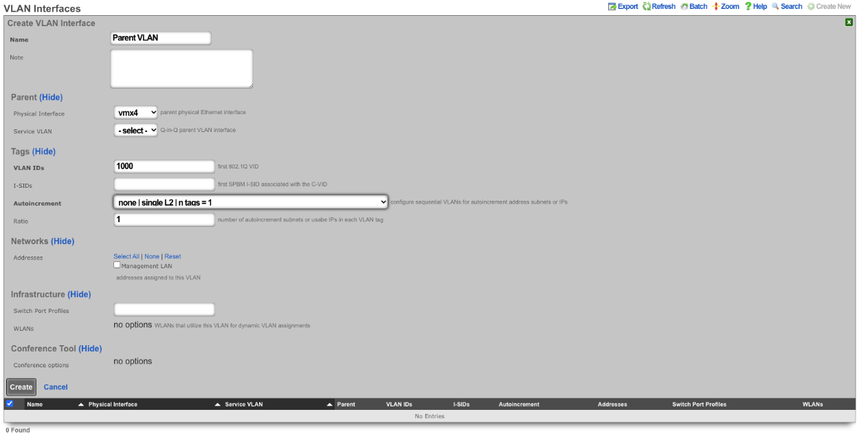
Next configure the VLAN pool that will be tied to the parent VLAN created in the previous step, these VLANs will be tied to IP address in that will be created in the next step as needed. Create a new VLAN Interface and give it a name. The Physical Interface should be unselected and the Service VLAN should be set to the Parent VLAN created in the previous step. The VLAN IDs should be set to the first VLAN to be used. Autoincrement should be set to per-ip , Ratio is set to 1. There is no need to select a Switch Port Profile as these VLANs will not be seen by the switch. Click Create.
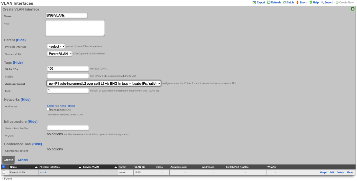
Next create a new Network Address , give it a name. Under Interface the Ethernet field should be set to -select- , and the VLAN field should be set to the VLAN created in the previous step. Enter the IP address in CIDR notation in the IP field. The Autoincrement and Span field should be set to 1. Checking the Create DHCP Pool box will automatically create a DHCP pool for the addresses. Click Create.
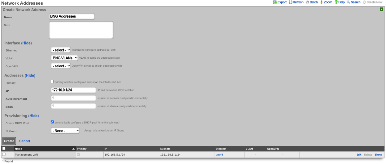
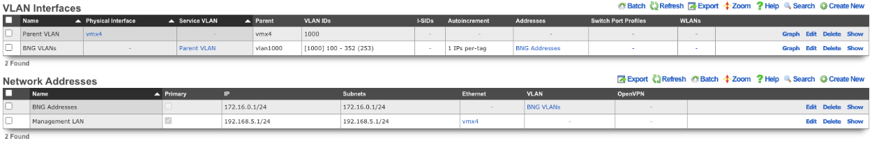
With this configuration we have a VLAN (VLAN 1000), that contains our BNG VLANs (VLANS 100-352) which allows for the BNG VLANs to be assigned individually to a single IP within the BNG Addresses that were configured. Multiple IPs can be assigned the same VLAN within the address pool as needed and each assignment only consumes a single IP instead of a minimum of 4.
The use of the Q-in-Q network architecture allows a single physical interface to be used with multiple autoincrement BNG interfaces as well as static or dynamically configured VLANs. For example:

Here we see multiple BNG interfaces are created to support distinct downstream distribution equipment. We also see that there is an additional SVLAN that is dedicated for management infrastructure. The standards based nature of the autoincrement BNG approach enables unparalleled flexibilty and diversity. Any VLAN-aware distribution equipment, wireline or wireless, may participate in an autoincrement BNG deployment. In fact, it is even possible to have a single distribution infrastructure composed of equipment from multiple vendors and even mixing different forms of technology. A single installation may use BNG to efficiently distribute public IP addresses across DSL, GPON, DOCSIS, fixed wireless and PLTE all within the same deployment.


