Wireless
The Wireless view presents the scaffolds associated with configuring the wireless distribution layer of your network, and monitoring/configuring the Wireless Access Points (WAPs) throughout your infrastructure.

Understanding Transmit Power
Transmit power (TX Power) is the RF power output by a WAP's radio when broadcasting signals to wireless clients. Proper power configuration is essential for optimal coverage, capacity, and interference management.
Note: This documentation applies to all supported wireless vendors (Ruckus, Aruba, Cambium, Extreme, Adtran, TP-Link, OpenWiFi, and others). The rXg provides a unified abstraction layer for TX power configuration, allowing operators to manage power settings consistently through the Access Point Zone, Profile, and WAP scaffolds regardless of the underlying controller or WAP hardware.
What is dBm?
Wireless power levels are measured in dBm (decibels relative to one milliwatt). This is a logarithmic scale where:
- 0 dBm = 1 milliwatt (reference point)
- Positive values = more than 1 mW (e.g., +20 dBm = 100 mW)
- Negative values = less than 1 mW (e.g., -10 dBm = 0.1 mW)
The logarithmic nature means: - Every +3 dB doubles the power - Every -3 dB halves the power - Every +10 dB multiplies power by 10 - Every -10 dB divides power by 10
TX Power Quick Reference
| TX Power (dBm) | Power (mW) | Typical Use Case |
|---|---|---|
| +30 dBm | 1000 mW | Maximum outdoor, long-range links |
| +27 dBm | 500 mW | High-power outdoor coverage |
| +24 dBm | 250 mW | Standard outdoor / large indoor |
| +20 dBm | 100 mW | Typical indoor maximum |
| +17 dBm | 50 mW | Medium indoor coverage |
| +14 dBm | 25 mW | High-density indoor |
| +10 dBm | 10 mW | Very high-density / small cells |
| +7 dBm | 5 mW | Micro-cells, close proximity |
WAP Hardware Power Capabilities
Not all WAPs can transmit at the same power levels. Maximum TX Power varies significantly based on:
- Hardware class - Enterprise outdoor WAPs have higher power amplifiers than indoor models
- Frequency band - 2.4 GHz radios typically support higher power than 5 GHz or 6 GHz
- Number of spatial streams - Power is divided across multiple antennas in MIMO configurations
- Form factor - Compact or low-cost WAPs often have lower maximum power
Typical Maximum TX Power by WAP Class:
| WAP Class | 2.4 GHz Max | 5 GHz Max | 6 GHz Max | Examples |
|---|---|---|---|---|
| Outdoor High-Power | +28 to +30 dBm | +25 to +27 dBm | +24 to +25 dBm | Outdoor sector, point-to-point |
| Outdoor Standard | +25 to +27 dBm | +23 to +25 dBm | +22 to +24 dBm | Outdoor omni, campus coverage |
| Indoor Enterprise | +22 to +25 dBm | +20 to +23 dBm | +20 to +22 dBm | CIG WF189, EdgeCore EAP |
| Indoor Standard | +20 to +22 dBm | +18 to +20 dBm | +18 to +20 dBm | Wall-mount, ceiling WAPs |
| Indoor Compact | +18 to +20 dBm | +16 to +18 dBm | N/A | Small office, desktop |
Important Considerations:
- Effective power is per-chain: A 4x4 MIMO WAP at +20 dBm total may only output +14 dBm per antenna chain
- Actual vs. configured: Setting TX Power to "Full" uses the WAP's hardware maximum, which may be lower than regulatory limits
- Band differences: The same WAP model will have different maximum power on each band - check specifications for each radio
- Current TX Power field: The WAP Radios scaffold displays the actual current TX Power in dBm, which reflects hardware capabilities and regulatory limits applied
Practical Tip: When planning coverage, use the TX Power values reported by deployed WAPs rather than assuming all WAPs operate at the same power level. This is especially important in mixed-model deployments.
Configuring TX Power
TX Power is configured as a relative reduction from a reference maximum, expressed in dB. Understanding the difference between configured power and actual power is critical.
Configured Power vs. Actual Power (OpenWiFi Specific)
The system uses two power values:
- Configured Power (reference maximum): A regulatory or system-defined maximum (e.g., 30 dBm for "Full")
- Actual Power: What the WAP hardware actually outputs, limited by its physical capabilities
The configured reduction is applied to the reference maximum, but the actual output is capped by the WAP's hardware maximum. This has important implications:
Example - OpenWiFi WAP with 26 dBm hardware maximum:
| Configuration | Configured Power | Actual Power | Effect |
|---|---|---|---|
| 0 (Full) | 30 dBm | 26 dBm | Capped at hardware max |
| -3 | 27 dBm | 26 dBm | Still capped at hardware max |
| -4 | 26 dBm | 26 dBm | Still at hardware max |
| -5 | 25 dBm | 25 dBm | Now actually reduced |
| -10 | 20 dBm | 20 dBm | Reduced |
Important: In this example, settings from Full (0) to -4 dB all produce the same actual power output of 26 dBm. The WAP cannot exceed its hardware capability, so small reductions from "Full" will have no effect until the configured power drops below the hardware maximum.
Configuration Reference
| Configuration Value | Reduction from Reference |
|---|---|
| 0 (Full) | No reduction (reference maximum) |
| -3 | Half power (-3 dB) |
| -6 | Quarter power (-6 dB) |
| -10 | One-tenth power (-10 dB) |
| -20 | One-hundredth power (-20 dB) |
| -99 (Minimum) | Lowest possible power |
Actual Power Varies by WAP Model
Because different WAPs, and different Radios within the same WAP, have different hardware maximums, the same configuration produces different actual power levels:
| Configuration | Indoor Compact | Indoor Enterprise | Outdoor |
|---|---|---|---|
| Hardware Max | 18 dBm | 23 dBm | 27 dBm |
| 0 (Full) | 18 dBm | 23 dBm | 27 dBm |
| -3 | 15 dBm | 20 dBm | 24 dBm |
| -6 | 12 dBm | 17 dBm | 21 dBm |
| -10 | 8 dBm | 13 dBm | 17 dBm |
Always verify actual operating power using the Current TX Power field in the WAP Radios scaffold, especially when fine-tuning power settings.
Configuration Hierarchy: TX Power can be set at multiple levels, with more specific settings overriding general ones:
- Access Point Zone (Network :: Wireless :: Access Point Zones) - Default for all WAPs in the zone. Configure using the TX Power fields (tx_power_24, tx_power_5, tx_power_6) per band.
- Individual WAP (Network :: Wireless :: Access Points) - Overrides zone settings for a specific WAP.
Note: Antenna gain is configured at the Access Point Profile level, not TX Power. See Antenna Gain Considerations for details.
Direct dBm Override (OpenWiFi Only)
OpenWiFi devices support an additional TX Power (dBm) field that sets the radio's transmit power directly in dBm, bypassing the relative reduction system described above. This is useful when you know the exact power level you want on the radio and don't want it translated through the plan-based conversion.
The valid range is 130 dBm.
Override priority:
- AP-level dBm override if set, used directly
- Zone-level dBm override if the AP's value is blank, the zone value is used
- Plan-based TX Power if both dBm overrides are blank, the existing relative reduction system is used
When a dBm override is set, the hardware will still cap the actual output at its maximum capability. For example, setting 30 dBm on an indoor AP with a 23 dBm hardware maximum will result in 23 dBm actual output.
TX Power and Client Signal Strength (RSSI)
The signal strength a client receives (RSSI) depends on the TX Power minus path loss:
Client RSSI TX Power + Antenna Gain - Path Loss
Example: A WAP transmitting at +20 dBm with +3 dBi antenna gain, and 60 dB path loss to the client:
Client RSSI 20 + 3 - 60 = -37 dBm (excellent signal)
| Client RSSI | Signal Quality | Expected Experience |
|---|---|---|
| -30 to -50 dBm | Excellent | Maximum speeds, very reliable |
| -50 to -60 dBm | Very Good | High speeds, reliable |
| -60 to -70 dBm | Good | Good speeds, occasional retries |
| -70 to -80 dBm | Fair | Reduced speeds, intermittent issues |
| -80 to -90 dBm | Poor | Slow speeds, frequent disconnections |
| Below -90 dBm | Unusable | Connection failures |
When to Adjust TX Power
| Scenario | Recommendation |
|---|---|
| Large open areas | Higher power for coverage |
| High-density venues (stadiums, conference rooms) | Lower power to reduce interference and improve capacity |
| Multi-floor buildings | Lower power to reduce floor-to-floor bleed |
| Adjacent WAPs on same channel | Lower power to reduce co-channel interference |
| Client roaming issues | Lower power to encourage clients to roam to closer WAPs |
| Coverage gaps | Higher power or additional WAPs |
Common Mistake: Setting TX Power too high in dense deployments. This causes: - Clients "stick" to distant WAPs instead of roaming to closer ones - Increased co-channel interference between WAPs - Reduced overall network capacity
Auto Cell Sizing
Note: Auto Cell Sizing is currently only available for Ruckus controllers. It is not supported for OpenWiFi or other vendors.
Auto Cell Sizing automatically adjusts TX Power based on the RF environment. When enabled:
- The system monitors neighboring WAPs and interference levels
- TX Power is dynamically reduced when conditions allow
- Coverage is maintained while minimizing interference
Requirements: - TX Power must be set to Full (0) - Background Scanning must be enabled for the same band - Available per band (2.4 GHz, 5 GHz)
Best For: Environments where RF conditions change (temporary events, variable occupancy) or where manual optimization is impractical.
Antenna Gain Considerations
Antenna gain (measured in dBi) adds to the effective radiated power:
Effective Radiated Power (EIRP) = TX Power + Antenna Gain
When using external antennas, configure the 2.4 GHz Antenna Gain and 5 GHz Antenna Gain fields (in dBi) in the Access Point Profiles scaffold (Network :: Wireless :: Access Point Profiles) so the system can: - Accurately calculate coverage - Ensure regulatory compliance (EIRP limits) - Properly coordinate Auto Cell Sizing
Regulatory Limits
TX Power is constrained by regulatory requirements based on:
- Country Code - Different countries have different maximum power limits
- Frequency Band - 2.4 GHz, 5 GHz, and 6 GHz have different limits
- Channel - DFS channels may have lower limits
- Indoor vs Outdoor - Outdoor operation often permits higher power
The Outdoor WAPs checkbox in Access Point Profiles enables outdoor-specific power and channel tables. Incorrect settings may violate local regulations.
Note: The rXg automatically enforces regulatory limits based on the configured Country Code. Setting TX Power to Full (0) will use the maximum power legally permitted, not necessarily the hardware maximum.
Data Flow: AP Provisioning and Client Onboarding
The following diagrams illustrate the end-to-end flow of how a wireless access point (WAP) is discovered, registered, configured, and begins serving clients.
AP Discovery, Registration, and Configuration Sync
sequenceDiagram
    participant AP as New Access Point
    participant SW as PoE Switch
    participant DHCP as DHCP Server<br/>(rXg)
    participant WC as WLAN Controller<br/>(Infrastructure Device)
    participant DB as rXg Database
    participant Op as Operator<br/>(Admin Console)

    Note over AP,Op: Phase 1  Physical Connection & IP Assignment

    AP->>SW: Power on (PoE) + Ethernet link
    SW-->>AP: PoE power + link negotiation
    AP->>DHCP: DHCP DISCOVER<br/>(management VLAN)
    DHCP->>DHCP: Select pool<br/>(match on VLAN/class)
    DHCP-->>AP: DHCP OFFER<br/>(IP, gateway, DNS)
    AP->>DHCP: DHCP REQUEST
    DHCP-->>AP: DHCP ACK<br/>(lease granted)

    Note over AP,Op: Phase 2  Controller Discovery & Adoption

    AP->>WC: Controller discovery<br/>(DNS/DHCP option/broadcast)
    WC->>AP: Adoption request
    AP-->>WC: Device info<br/>(MAC, model, firmware, serial)

    alt OpenWiFi AP
        AP->>WC: CSR (Certificate Signing Request)
        WC->>WC: Sign certificate (mTLS)
        WC-->>AP: Signed certificate
        AP->>WC: mTLS connection established
    else Ruckus / Other Vendor
        AP->>WC: Direct adoption<br/>(vendor protocol)
        WC-->>AP: Adoption confirmed
    end

    WC->>DB: Create/update AccessPoint record<br/>(MAC, model, IP, firmware, online=true)

    Note over AP,Op: Phase 3  Profile Assignment & Config Push

    Op->>DB: Assign AP to Access Point Profile<br/>(or use zone default)
    DB-->>WC: Config change trigger

    WC->>AP: Push configuration
    Note right of WC: WLAN SSIDs + encryption<br/>Channel assignments<br/>TX power settings<br/>VLAN mappings<br/>RADIUS server config<br/>Tunnel parameters (if SoftGRE)

    AP->>AP: Apply radio configuration<br/>(per band: 2.4/5/6 GHz)
    AP-->>WC: Config sync confirmed
    AP->>AP: Begin broadcasting SSIDs
SoftGRE Tunnel Establishment
When a WLAN is configured with tunneling enabled, the AP establishes a GRE tunnel back to the rXg for centralized traffic processing.
sequenceDiagram
    participant CL as Wireless Client
    participant AP as Access Point
    participant RXG as rXg Gateway<br/>(GRE Endpoint)
    participant PF as Packet Filter<br/>(Policy Engine)

    Note over CL,PF: SoftGRE Tunnel Setup

    AP->>RXG: GRE tunnel initiation<br/>(to gre_tunnel_gateway_ip)
    RXG->>RXG: Create GRE pseudo-interface<br/>(greN + bridgeN)
    RXG-->>AP: Tunnel established

    Note over CL,PF: Client Traffic via Tunnel

    CL->>AP: Associate with SSID
    CL->>AP: Data frame<br/>(L2 Ethernet)
    AP->>RXG: Encapsulate in GRE tunnel<br/>(L2oGRE: original frame + GRE header)
    RXG->>RXG: Decapsulate GRE<br/>(extract original L2 frame)
    RXG->>PF: Apply policy enforcement<br/>(NAT, bandwidth queues,<br/>captive portal redirect)
    PF->>RXG: Forward to Internet<br/>(or redirect to portal)

    Note over CL,PF: Return Traffic

    RXG->>RXG: Receive Internet response
    PF->>RXG: Policy applied (QoS shaping)
    RXG->>AP: Encapsulate in GRE tunnel
    AP->>CL: Deliver to client<br/>(L2 frame)
Wireless Client Authentication Flow (802.1X / MAC Auth)
sequenceDiagram
    participant CL as Wireless Client
    participant AP as Access Point
    participant RAD as RADIUS Server<br/>(rXg)
    participant DB as rXg Database

    Note over CL,DB: MAC Authentication Bypass

    CL->>AP: Association request
    AP->>RAD: Access-Request<br/>(User-Name = client MAC,<br/>Calling-Station-Id = client MAC)
    RAD->>DB: Lookup MAC in RADIUS realm
    DB-->>RAD: Match found  policy + VLAN

    RAD-->>AP: Access-Accept<br/>(Tunnel-Type = VLAN,<br/>Tunnel-Medium-Type = IEEE-802,<br/>Tunnel-Private-Group-Id = VLAN tag)

    AP->>AP: Assign client to DVLAN
    AP-->>CL: Association confirmed<br/>(on assigned VLAN)

    Note over CL,DB: 802.1X EAP Authentication

    CL->>AP: EAPOL-Start
    AP->>RAD: Access-Request<br/>(EAP-Message = EAP identity)
    RAD->>RAD: Evaluate RADIUS realm<br/>(select backend server by priority)

    loop EAP Exchange
        RAD-->>AP: Access-Challenge<br/>(EAP method negotiation)
        AP-->>CL: EAP-Request
        CL->>AP: EAP-Response<br/>(credentials)
        AP->>RAD: Access-Request<br/>(EAP-Message = response)
    end

    RAD->>RAD: Validate credentials<br/>(local DB / LDAP / external RADIUS)
    RAD-->>AP: Access-Accept<br/>(VLAN assignment, Session-Timeout,<br/>Class attributes)

    AP->>AP: Assign DVLAN + open port
    AP-->>CL: EAP-Success + 4-way handshake
    CL->>CL: DHCP on assigned VLAN

    Note over CL,DB: Accounting

    AP->>RAD: Accounting-Request<br/>(Acct-Status-Type = Start)
    RAD->>DB: Create LoginSession record
Scan-Based RRM (ACS and TX Power Optimization)
The rXg includes a vendor-independent scan-based Radio Resource Management (RRM) system that complements the existing map-based RRM. While map-based RRM requires AP placement on floor plans, scan-based RRM uses live WiFi scan data to optimize channel selection and transmit power levels without map dependencies.
The scheduling logic, decision algorithms, and threshold configuration are fully vendor-independent. Vendor-specific execution (e.g., how to restart a radio or trigger a WiFi scan) is handled by pluggable concern modules. Currently supported: OpenWiFi WSS.
Automatic Channel Selection (ACS) Scheduling
ACS scheduling automatically triggers channel reselection on WAPs with radios configured for auto-channel. It uses a hybrid opportunistic + fallback approach to minimize client disruption while ensuring channels are periodically optimized.
ACS Workflow
                        +------------------+
                        |    Every Hour    |
                        |      (24/7)      |
                        +--------+---------+
                                 |
                                 v
          +-------------------------------------------+
          | For each Zone with ACS Scheduling Enabled |
          +--------------------+----------------------+
                               |
                               v
               +------------------------------+
               | Is this a scheduled hour?    |
               | (fallback, +6h, +12h, +18h)  |
               +---------------+--------------+
                               |
                   +-----------+-----------+
                   |                       |
                  YES                      NO
                   |                       |
                   v                       v
        +-----------------+       +---------------+
        | Is this the     |       | Skip zone     |
        | fallback hour?  |       | (not aligned) |
        +--------+--------+       +---------------+
                 |
           +-----+--------------+
           |                    |
          YES                   NO
           |                    |
           v                    v
  +---------------+  +---------------------+
  | FORCE MODE    |  | OPPORTUNISTIC MODE  |
  | (all radios)  |  | (idle radios only)  |
  +-------+-------+  +----------+----------+
          |                     |
          +----------+----------+
                     |
                     v
      +--------------------------------+
      | For each online WAP            |
      | (staggered 30 seconds apart)   |
      +----------------+---------------+
                       |
                       v
          +---------------------------+
          | WAP has auto-channel      |
          | radio? (channel = 0)      |
          +--------------+------------+
                         |
              +----------+----------+
              |                     |
             YES                    NO
              |                     |
              v                     v
     +------------------+         SKIP
     | Force mode?      |
     +---------+--------+
               |
         +-----+----------------+
         |                      |
        YES                    NO
         |                      |
         v                      v
  +-----------+  +----------------------------+
  | Restart   |  | For each radio:            |
  | ALL       |  |   auto-channel?            |
  | radios    |  |   telemetry fresh? (<5min) |
  +-----------+  |   0 connected clients?     |
                 +--------------+-------------+
                                |
                          +-----+-----+
                          |           |
                        ALL YES     ANY NO
                          |           |
                          v           v
                   +-----------+  +-----------+
                   | Restart   |  | Skip      |
                   | that      |  | that      |
                   | radio     |  | radio     |
                   +-----------+  +-----------+
ACS Modes
- Opportunistic mode (every 6 hours, aligned to fallback hour): Individual idle radios (0 connected clients with fresh telemetry) are restarted to trigger channel reselection. Radios with connected clients are skipped no client disruption occurs.
- Fallback mode (at configured fallback hour, default 4am local time): All radios are restarted regardless of client count. This ensures every radio gets optimized at least once per day, even radios that always have clients connected.
The 6-hour cycle runs at: fallback hour, fallback+6h, fallback+12h, fallback+18h. For example, with the default fallback hour of 4am, cycles run at 4am, 10am, 4pm, and 10pm.
Staggering and Capacity
WAPs are processed with 30-second stagger intervals to prevent thundering herd effects on both the rXg and the wireless controller. Each zone receives a unique offset based on its ID to further distribute load when multiple zones share the same fallback hour.
A 6-hour cycle supports up to 720 WAPs (6 hours x 120 WAPs/hour at 30-second intervals). If the number of online WAPs exceeds this capacity, a warning is logged suggesting the operator stagger fallback hours across zones.
ACS Trigger Mechanism
When ACS is triggered on a radio configured with channel = auto:
- A radio restart command is sent to the WAP
- The radio's wireless interface goes down briefly
- The access point runs the ACS algorithm during radio startup, surveying the RF environment
- An optimal channel is selected based on current interference conditions
- The radio comes back up on the new channel
- Clients automatically reconnect (typically within 1-2 seconds)
Per-radio restarts allow optimizing one band at a time without affecting other bands. For example, the 5 GHz radio can be restarted while the 2.4 GHz and 6 GHz radios continue serving clients.
Typical ACS scan duration by band:
| Band | Typical Duration | Notes |
|---|---|---|
| 2.4 GHz | ~3-5 seconds | Fewer channels to scan |
| 5 GHz | ~5-10 seconds | More channels; DFS channels excluded by default |
| 6 GHz | ~30-50 seconds | Many channels to survey |
ACS Configuration
Zone-level settings (Network :: Wireless :: Access Point Zones):
| Setting | Type | Default | Description |
|---|---|---|---|
| Enable ACS Scheduling | boolean | false | Activates automatic channel optimization for this zone |
| ACS Fallback Hour | integer (0-23) | 4 | Hour in zone-local time for forced channel reselection |
Per-WAP settings (Network :: Wireless :: Access Points):
| Setting | Type | Default | Description |
|---|---|---|---|
| Exclude from ACS Scheduling | boolean | false | Skip this WAP during ACS scheduling |
Prerequisites: - WAP must have at least one radio with channel set to auto (channel override = 0) - WAP must be online and connected to the controller - WAP must be managed by a controller that supports scan-based RRM
ACS Client Impact
| Scenario | Impact |
|---|---|
| Opportunistic ACS on idle radio | None radio has 0 clients |
| Opportunistic ACS skipped | None radio has clients, waits for fallback |
| Fallback ACS (all radios) | Brief disconnection (~1-2 seconds) during radio restart; clients auto-reconnect |
ACS Edge Cases
- WAP goes offline during scheduled ACS: The job checks the WAP's online status before execution and skips offline WAPs
- Zone timezone not set: Falls back to UTC
- ACS scan fails: Logged as failed; WAP continues operating on its current channel
- Radio has stale telemetry (>5 minutes old): Skipped in opportunistic mode client count cannot be trusted
- Mixed radio state (e.g., 2.4 GHz has 0 clients, 5 GHz has clients): In per-radio mode, only the idle 2.4 GHz radio is restarted; the 5 GHz radio is left untouched
TX Power Optimization
TX Power optimization analyzes neighbor AP RSSI observations to automatically adjust transmit power levels, reducing co-channel interference while maintaining client coverage. The algorithm uses a neighbor-based approach the industry standard used by enterprise vendors like Cisco, Aruba, and Ruckus with client RSSI as a safety constraint.
TX Power Optimization Workflow
 SCHEDULING (Hourly Check)
 --------------------------

    +-------------------+     +-------------------------------------+
    |  Scheduler        |---->|  TxPowerOptimizationJob             |
    |  (every hour)     |     |                                     |
    +-------------------+     |  - Check current hour per zone      |
                              |  - Find zones where hour matches    |
                              |  - Trigger WiFi scans on all WAPs   |
                              |  - Wait for scan data ingestion     |
                              |  - Queue per-AP job for each WAP    |
                              +------------------+------------------+
                                                 |
                                                 v
                    +--------------------------------------------+
                    |  For each zone where:                      |
                    |    tx_power_optimization_enabled = true    |
                    |    tx_power_optimization_hour = local hour |
                    |                                            |
                    |  For each online, non-excluded WAP:        |
                    |    1. Trigger WiFi scan (collect neighbor  |
                    |       BSSID data)                          |
                    |    2. Wait for scan ingestion              |
                    |    3. Schedule TxPowerApJob                |
                    +--------------------+-----------------------+


 PER-WAP OPTIMIZATION (TxPowerApJob)
 ------------------------------------

                    +-------------------------------+
                    |  Cooldown Check               |
                    |  Last optimization > 1 hour?  |
                    +---------------+---------------+
                                    |
                         +----------+----------+
                         |                     |
                        YES                    NO --> Skip (too soon)
                         |
                         v
            +----------------------------+
            |  For each band: 2G, 5G, 6G |
            +--------------+-------------+
                           |
                           v
    +------------------------------------------------------+
    |                  DECISION ENGINE                     |
    |                                                      |
    |  1. Query NeighborBssidObservation                   |
    |     - Find observations where this WAP sees our      |
    |       OTHER WAPs on the SAME channel (last 24h)      |
    |     - Get MAX(rssi) = strongest_neighbor             |
    |                                                      |
    |  2. Query RadioMetric                                |
    |     - Get average rssi_min for this radio (last 24h) |
    |     - This is the client RSSI floor (safety check)   |
    |                                                      |
    |  3. Apply Decision Logic (see matrix below)          |
    +------------------------------------------------------+
                             |
                             v
                    +----------------+
                    | Power changed? |
                    +--------+-------+
                             |
                  +----------+----------+
                  |                     |
                 YES                    NO --> Done
                  |
                  v
    +-------------------------------+
    |  Update AccessPoint           |
    |  tx_power_24/5/6 = new_value  |
    |  Save triggers config sync    |
    +-------------------------------+
TX Power Decision Matrix
The algorithm evaluates two inputs neighbor RSSI (how strongly our other WAPs see this WAP on the same channel) and client RSSI (the minimum signal strength of connected clients) and applies the following decision logic:
| Neighbor RSSI | Client RSSI | Action | Rationale |
|---|---|---|---|
| > -50 dBm (strong) | > -70 dBm (good) | REDUCE power by step size | Neighbors see us too strongly (interference); clients have headroom to tolerate reduction |
| > -50 dBm (strong) | < -70 dBm (weak) | NO CHANGE | Interference present but clients need the power cannot safely reduce |
| -80 to -50 dBm | any | NO CHANGE | Optimal range neighbor signal is neither too strong nor too weak |
| < -80 dBm (weak) | < -75 dBm (poor) | INCREASE power by step size | Coverage gap clients are struggling and neighbors barely see us |
| < -80 dBm (weak) | > -75 dBm (ok) | NO CHANGE | Neighbors are weak but clients are fine no action needed |
| null (no data) | any | NO CHANGE | Insufficient neighbor data to make a decision |
Why neighbor-based power adjustment? - High data reliability: We control both WAPs, so RSSI observations between our own WAPs are trustworthy - Proactive: Detects interference potential before clients are affected - Industry standard: This is how Cisco RRM, Aruba ARM, and Ruckus ChannelFly approach TX power management - Client RSSI alone is ambiguous a phone close to the WAP has high RSSI regardless of AP power, which does not indicate excessive power
TX Power Optimization Example
  Before Optimization:
  +---------+                              +---------+
  |  WAP-A  | ------ -45 dBm ------------> |  WAP-B  |
  | 30 dBm  |        (too strong!)         | 30 dBm  |
  +---------+                              +---------+
       |                                        |
       | clients: -55 dBm avg                   | clients: -60 dBm avg
       | (good headroom)                        | (good headroom)

  After Optimization (2 iterations, 1 hour apart):
  +---------+                              +---------+
  |  WAP-A  | ------ -51 dBm ------------> |  WAP-B  |
  | 27 dBm  |        (now optimal)         | 27 dBm  |
  +---------+                              +---------+
       |                                        |
       | clients: -58 dBm avg                   | clients: -63 dBm avg
       | (still good)                           | (still good)

  Result: Reduced co-channel interference while maintaining good client signal.
Same-Channel Filtering
The algorithm only considers same-channel neighbors when evaluating interference. WAPs operating on different channels do not cause co-channel interference (CCI), even if they are physically close. This means:
- A 5 GHz WAP on channel 36 only compares against other WAPs also on channel 36
- WAPs on adjacent but non-overlapping channels (e.g., 36 vs 40) are not considered
- This filtering dramatically reduces false positives and ensures power adjustments target actual interference
Config Sync Flow
When the algorithm determines a power change is needed:
- The
tx_power_24,tx_power_5, ortx_power_6field on the AccessPoint record is updated AccessPoint.save!triggers anafter_commitcallback for configuration synchronization- The infrastructure device sync job builds the radio configuration with the new TX power value
- The configuration is pushed to the WAP via the controller
- The WAP applies the new power setting and the affected radio reloads
- The device clamps the requested power to regulatory maximums automatically
Power changes can be applied per-radio only the affected band's radio reloads, minimizing client disruption.
TX Power Configuration
Zone-level settings (Network :: Wireless :: Access Point Zones):
| Setting | Type | Default | Description |
|---|---|---|---|
| Enable TX Power Optimization | boolean | false | Activates power optimization for this zone |
| TX Power Optimization Hour | integer (0-23) | 3 | Hour in zone-local time to run daily optimization |
| Neighbor Too Strong | integer (dBm) | -50 | RSSI threshold above which power should be reduced |
| Neighbor Too Weak | integer (dBm) | -80 | RSSI threshold below which power may be increased |
| Client RSSI Floor | integer (dBm) | -75 | Minimum acceptable client signal strength |
| Client RSSI Headroom | integer (dBm) | -70 | Client signal strength that allows safe power reduction |
| Step Size | integer (dBm) | 3 | Power adjustment increment per optimization cycle (range: 1-10) |
Per-WAP settings (Network :: Wireless :: Access Points):
| Setting | Type | Default | Description |
|---|---|---|---|
| Exclude from TX Power Optimization | boolean | false | Skip this WAP during TX power optimization |
TX Power Safety Mechanisms
- Gradual changes: Power is adjusted in configurable step sizes (default 3 dBm) to avoid oscillation and allow metrics to stabilize between changes
- 1-hour cooldown: After any power change, the WAP is excluded from further adjustments for 1 hour to allow client RSSI metrics to reflect the new power level
- Client RSSI floor: Power is never reduced if clients are already below the headroom threshold, even if neighbor interference is high
- Regulatory clamping: The WAP automatically clamps requested power to the regulatory maximum for its country code, band, and channel the system does not need to track per-device limits
- 24-hour data window: Neighbor and client RSSI data is evaluated over a 24-hour window to smooth out transient conditions
RRM Event Audit Trail
All ACS and TX Power actions are recorded in the RRM Events table for audit and debugging:
| Event Type | Description |
|---|---|
| ACS Fallback | Forced ACS at fallback hour (all radios restarted) |
| ACS Opportunistic | Opportunistic ACS on idle radios |
| ACS Manual | Manual ACS trigger by administrator |
| TX Power Adjust | TX power optimization adjustment |
| WiFi Scan | WiFi scan triggered for neighbor data collection |
Each event records the execution status (executed, skipped, or failed), the skip reason if applicable, and a rich decision context including neighbor RSSI values, client RSSI floor, and the thresholds that were evaluated. For TX power changes, the previous and new power values are recorded per band.
WLAN Controllers
An entry in the WLAN controllers scaffold defines a piece of wireless equipment with which the rXg will communicate for the purpose of effecting dynamic VLAN changes when necessary due to a policy shift for a device on the network.
When a device's VLAN assignment has changed due to a policy shift, the rXg will connect to the WLAN controller associated with the device's RADIUS realm via the protocol specified in the configuration, and force a disconnect/reconnect, which will reinitiate the RADIUS authentication process, thereby resulting in the new VLAN assignment being applied to the client device.
The name field is an arbitrary string descriptor used only for administrative identification. Choose a name that reflects the purpose of the record. This field has no bearing on the configuration or settings determined by this scaffold.
The device field specifies the type of equipment being configured. Choose the appropriate option from the supported device types drop-down menu.
Aruba Device Types: When configuring Aruba wireless equipment, select the appropriate device type based on your deployment:
| Device Type | Description |
|---|---|
| ArubaOS | Aruba Mobility Master or Mobility Controller (on-premises controller) |
| Aruba Central | Aruba Central cloud management platform |
| Aruba IAP | Aruba Instant Access Point (standalone or virtual controller mode) |
The host field specifies the IP address or hostname of the WLAN controller for API and management communication.
The username and password fields provide the credentials for authenticating API connections to the controller. These must match the administrative account configured on the controller.
The enable telemetry boolean completely controls whether the rXg will attempt to receive and process telemetry data at all.
The Instrument from Telemetry checkbox results in the rXg using telemetry data to instrument the WAPs and Wireless Clients for this controller, instead of the regular API integration. If telemetry is enabled, the rXg will always instrument radio and client data, regardless of whether instrument from telemetry is enabled.
Enabling the Monitoring checkbox results in the rXg attempting to import and synchronize WAPs from the device, as well as perform ping monitoring of the Infrastructure Device itself, and collect CPU and Memory statistics, where possible.
The SNMP community field specifies the SNMP community string that will be used when attempting to gather CPU and/or Memory information, or WAP data from WLAN controllers where an API is not available.
The NB portal password and NB portal usernames are used when executing API calls against RUCKUS's northbound portal interface. These must correlate with what is configured in the controller.
The Telemetry username and Telemetry password are used when authenticating an MQTT session with this WLAN Controller. These must correlate with what is configured in the controller's northbound data streaming subscriptions.
Vendor Specific Configuration Examples
For Infrastructure Devices which support configuration management, the Config sync status column contains a link that allows the operator to access bootstrap instructions and enable synchronization.
When enabling automatic WLAN controller configuration management, the operator should ensure that the timezone and country code set in the Device Options scaffold are accurate as they will be used when configuring wireless infrastructure.
After initial bootstrapping and network connectivity is established, the operator may download a running configuration backup or compare the current running configuration to the expected configuration, based on the associated configuration elements. If changes are needed, they may be pushed to the controller. After successfully synchronizing manually the first time, future configuration changes will be pushed to the device whenever relevant configuration changes are made in the database.
Vendor Specific Configuration Examples
The note field is a place for the administrator to enter a comment. This field is purely informational and has no bearing on the configuration settings.
Piglet Sensor
Piglets are small, low-cost, Raspberry Pi-based network sensors that can be used for monitoring network performance from the client's perspective. They support ping tests, speed tests, and WLAN-scoping to validate wireless network quality. Adding a WLAN Controller with a device type of "Piglet" and a host address of "127.0.0.1" in this scaffold will allow the Piglet sensors to discover the rXg for adoption. See Piglet Sensors for complete documentation.
WLANs
An entry in the WLANs scaffold defines a wireless network that you wish to deploy on a supported WLAN controller.
The SSID field specifies the WLAN SSID that will be broadcast and visible to users.
The Hidden SSID checkbox prevents the SSID from being broadcast in beacon frames. Clients must know the network name to connect.
The Encryption selection specifies the encryption algorithm which will be used for this WLAN: - None: Open network with no encryption - WEP 128-bit: Legacy encryption (not recommended for security reasons) - WPA2: AES-CCMP encryption (IEEE Std 802.11i) - WPA3: Enhanced encryption with SAE authentication (IEEE Std 802.11-2020) - WPA2/WPA3: Transitional mode supporting both WPA2 and WPA3 clients - WPA Mixed: Supports both TKIP and AES clients (legacy compatibility) - OWE: Opportunistic Wireless Encryption for open networks with encryption
The Authentication selection specifies the type of authentication that should take place in order for users to join the network: - None: No authentication required - MAC Authentication Bypass: RADIUS authentication using client MAC address - Multiple PSK (DPSK): Dynamic Pre-Shared Key allowing unique keys per device or account - IEEE Std 802.1X EAP: Enterprise authentication using RADIUS and EAP - IEEE Std 802.1X EAP-PSK: Combines EAP authentication with a pre-shared key - IEEE Std 802.1X EAP-MAC: Combines EAP authentication with MAC-based fallback
In order for Dynamic VLANs to be assigned, authentication must utilize MAC Authentication Bypass or one of the IEEE Std 802.1X methods.
The Management Frame Protection (MFP) selection controls IEEE Std 802.11w protection for management frames: - Disabled: No management frame protection - Capable: Clients may use MFP if supported - Required: Only clients supporting MFP can connect
The Default VLAN field specifies the VLAN that users should be placed into, assuming it is not overridden by Dynamic VLAN behavior.
The PSK (Pre-Shared Key) field specifies the network password when using WPA2, WPA3, or WPA Mixed encryption without IEEE Std 802.1X authentication. The key must be 8-63 characters for ASCII or 64 hexadecimal characters. This field is not used when encryption is set to None or when using Multiple PSK (DPSK) authentication.
The Hotspot 2.0 checkbox enables Passpoint/Hotspot 2.0 functionality for this WLAN. When enabled, authentication is locked to IEEE Std 802.1X EAP and encryption to WPA2. A Hotspot WLAN Profile must be associated to configure the Passpoint parameters.
Radio Band Enablement
The Enabled checkboxes allow the operator to enable or disable a WLAN for a particular radio across all profiles where it is utilized: - Enabled 2.4 GHz: Enable the WLAN on 2.4 GHz radios - Enabled 5 GHz Lower: Enable the WLAN on lower 5 GHz channels (UNII-1) - Enabled 5 GHz Upper: Enable the WLAN on upper 5 GHz channels (UNII-2/3) - Enabled 6 GHz: Enable the WLAN on 6 GHz radios (Wi-Fi 6E)
Client Isolation
The Client Isolation checkbox prevents wireless clients on this WLAN from communicating directly with each other. Traffic between clients is blocked at the WAP level, forcing all communication through the network gateway. This is useful for guest networks and hotspot deployments.
Tunnel Configuration
The Tunnel checkbox instructs WAPs to build a tunnel to the controller or some other location, depending on the vendor, instead of locally bridging the client traffic.
The GRE Tunnel Type selection specifies the tunnel encapsulation method: - Ruckus GRE: Standard Ruckus GRE tunneling - SoftGRE: Software-based GRE tunneling compatible with rXg
The GRE Tunnel Gateway IP field specifies the destination IP address for GRE tunneled traffic. This is typically the rXg or another concentrator device.
The IPsec Option association allows selecting an IPsec configuration for encrypting tunnel traffic.
Application Examples: - RUCKUS SoftGRE Tunnel
RADIUS and VLAN Configuration
Dynamic VLANs require the association of at least one VLAN record which is tied to a RADIUS Realm.
The RADIUS Accounting checkbox instructs the WAP to send accounting information to the RADIUS server as users join, use, and leave the network.
The Access Point Profiles selection specifies which Profiles should include this WLAN.
Hotspot WLAN Profiles
An entry in the Hotspot WLAN Profiles scaffold becomes available for selection on a WLAN which has the hotspot20 boolean enabled, and is used to configure the Hotspot 2.0 parameters of a WLAN. The WLAN profile is comprised of several components:
- Operator Profile: Specifies the descriptive information about the operator of the wireless network
- Identity Providers: Specifies the identity providers that will be used to authenticate users
- Home Organization IDs: Specifies the home service provider network.
- Public Land Mobile Networks (PLMN): Used to match mobile network identities (e.g., SIM-based authentication). This allows for configuration of the MCC / MNC (Mobile Country Code and Mobile Network Code) that define the PLMN.
- Hotspot RADIUS Realms: Specifies RADIUS realms used to route authentication requests.
- EAP Methods: Defines authentication methods used for client authentication.
- Authorization Settings: Used to apply access policy or vendor-specific extensions.
An example config template that creates a Hotspot WLAN Profile is as follows:
---
HsWlanProfile:
- name: OpenRoaming Profile
internet_option: true
access_network_type: FREE_PUBLIC
ipv4_address_type: SINGLE_NATED_PRIVATE
ipv6_address_type: UNAVAILABLE
hs_operator_profile:
  name: OpenRoaming Operator
  domain_name: rgnets.com
  friendly_name: RG Nets
hs_identity_providers:
- name: OpenRoaming Provider
  hs_home_oids:
  - name: WBA OpenRoaming RCOI
    oi: 5a03ba0000
  hs_radius_realms:
  - name: OpenRoaming-Realm
    encoding: RFC4282
    hs_eap_methods:
    - name: EAP-1
      eap_type: EAP_TTLS
      hs_auth_settings:
      - name: Auth-1
        auth_info: Non
        auth_type: MSCHAPV2
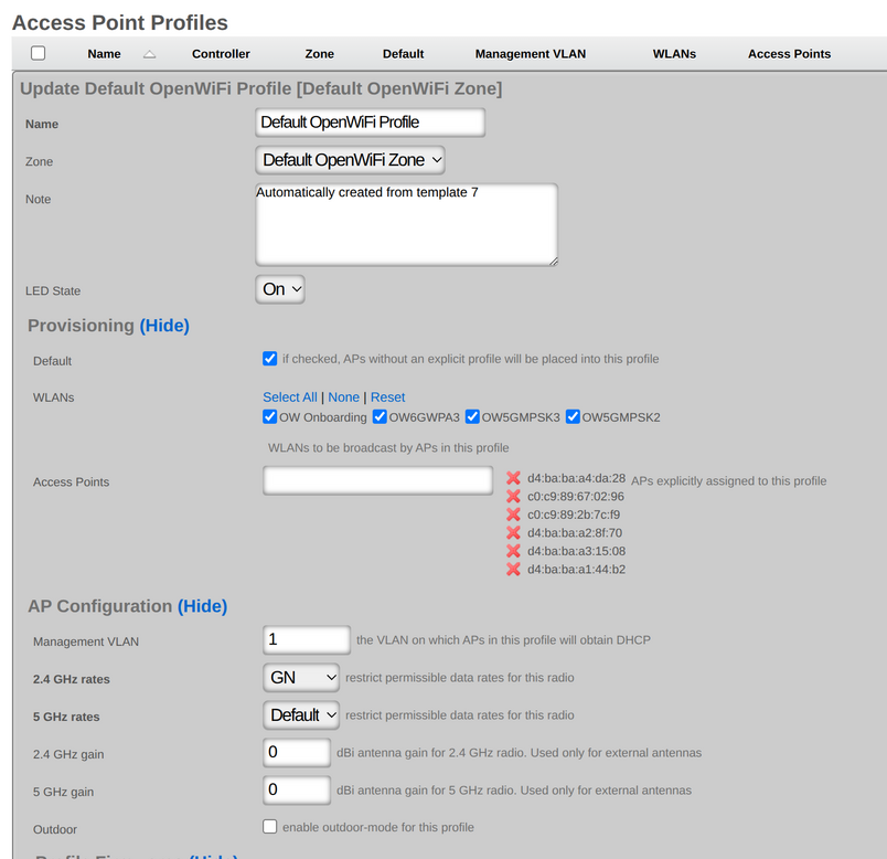
WAP Profiles
An entry in the Access Point Profiles scaffold defines a set of common configuration parameters to be applied to a set of WAPs.
The Default checkbox indicates that this Profile will be the default Profile for this Infrastructure Device. Any WAP which has not been explicitly assigned to a Profile will be placed into this Profile.
The WLANs association defines which WLANs will be broadcast on WAPs that fall into this Profile.
The Access Points association allows the operator to explicitly assign a profile to one or more WAPs. Selected WAPs which do not belong to the Infrastructure Device that the Profile is assigned to will be automatically deselected upon saving.
The Management VLAN field specifies which VLAN the WAPs in this profile will use to attempt to obtain an IP address via DHCP.
The 2.4 GHz Data Rates and 5 GHz Data Rates fields allow the operator to restrict the types of devices that may join the network to only those supporting a specific subset of data rates. By default, IEEE Std 802.11b rates are disabled to improve network performance.
The 2.4 GHz Antenna Gain and 5 GHz Antenna Gain fields allow the operator to specify antenna gain values (in dBi) that will be applied to WAPs which use external antennas.
The Outdoor WAPs checkbox instructs the system to enable or disable outdoor power and channel tables for the radios in order to be compliant with regulatory rules.
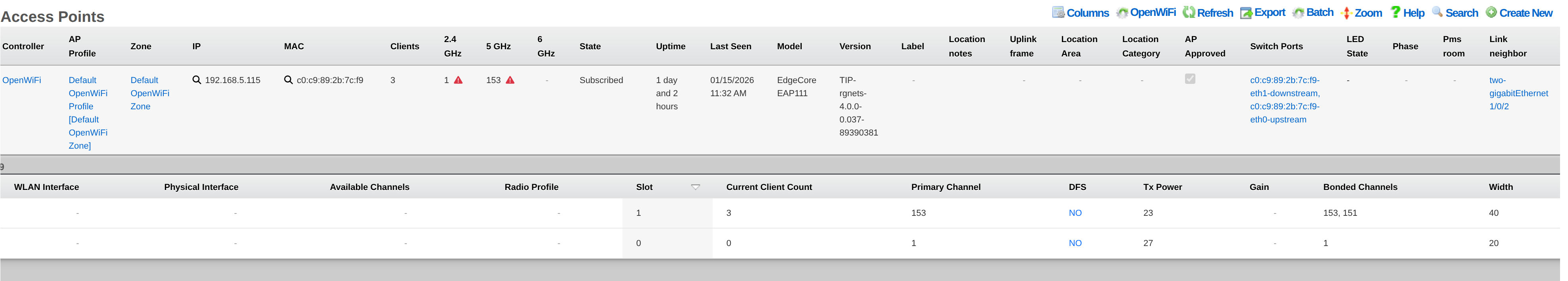
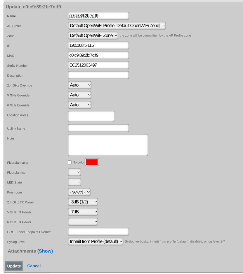
Wireless Access Points
Entries in the Access Points scaffold are created automatically by enabling the Monitoring checkbox on a supported wireless controller's Infrastructure Device. Status and statistics are gathered on an ongoing basis via API and/or SNMP.
After creation, the operator may reassign a WAP's Access Point Profile in order to control the WLAN and radio settings applied to it. WAP details are updated on a regular basis via background interaction with the Infrastructure Device.
The Name field displays the WAP's configured name or hostname.
The MAC field shows the WAP's primary MAC address, used for identification.
The IP field displays the WAP's current IP address.
The Model field indicates the WAP hardware model (e.g., R650, WF189).
The Version field shows the currently installed firmware version.
The Online indicator shows whether the WAP is currently reachable and operational.
The Client Count field displays the number of wireless clients currently connected to this WAP.
Channel Configuration
Each WAP supports channel configuration across three frequency bands: 2.4 GHz, 5 GHz, and 6 GHz.
The Channel fields (channel_24, channel_5, channel_6) display the current operating channel for each band.
The Channel Override fields allow operators to manually specify a channel, overriding automatic channel selection.
The Channel Plan fields show planned channel assignments for scheduled optimization.
Power and Radio Settings
The TX Power fields (tx_power_24, tx_power_5, tx_power_6) control transmit power levels per band.
The LED State field controls the WAP's LED indicators (On, Off, or Blink).
The Syslog Level field configures logging verbosity (1=Alert through 7=Debug).
Geographic and Floor Plan Integration
The Latitude and Longitude fields store the WAP's geographic coordinates for mapping.
The X and Y fields store floor plan coordinates for indoor positioning.
The Location and Location Notes fields provide human-readable location descriptions.
OpenWiFi Certificate Management
For OpenWiFi WAPs, the Approved checkbox indicates mTLS certificate approval status.
The Certificate field stores the WAP's client certificate for secure communication.
The CSR field contains the Certificate Signing Request for certificate enrollment.
The Firmware Compatibility field specifies the device type string for firmware matching (e.g., cig_wf189).
The GRE Endpoint field allows per-WAP override of the GRE tunnel destination IP address.
WAP Radios
Entries in the Access Point Radios scaffold are created automatically by enabling the Monitoring checkbox on a supported wireless controller's Infrastructure Device. Status and statistics are gathered on an ongoing basis via API and/or SNMP.
Each WAP typically has multiple radios, one per frequency band (2.4 GHz, 5 GHz, and optionally 6 GHz).
The MAC field displays the radio's BSSID (Basic Service Set Identifier).
The Slot ID field identifies the radio slot within the WAP hardware.
The Access Point association links the radio to its parent WAP.
Current Radio Status
The Current Channel field shows the channel the radio is currently operating on.
The Current Channel Width field displays the current channel bandwidth (20, 40, 80, or 160 MHz).
The Current TX Power field shows the current transmit power level in dBm.
The Current Gain field displays the current antenna gain setting.
The Current HW Mode field indicates the active IEEE Std 802.11 mode (a/b/g/n/ac/ax).
The Current Client Count field shows how many clients are connected via this radio.
The Current Frequencies field lists the frequencies in use, relevant for bonded channels.
Radio Capabilities
The Available Channels field lists channels the radio hardware supports.
The Available HW Modes field shows supported IEEE Std 802.11 modes.
Monitor Mode
The Monitor Mode checkbox enables the radio for passive scanning and testing rather than serving clients. When enabled, the radio can be associated with Ping Targets and Speed Tests for wireless network diagnostics.
Note: Monitor mode cannot be enabled when the radio has active Ping Target or Speed Test associations in client-serving mode.
Radio Profile Association
The Access Point Radio Profile association allows assigning a radio profile to control channel selection and hardware mode preferences.
Metrics and Neighbor Detection
WAP Radios collect ongoing metrics including channel utilization, received signal strength, and transmit/receive statistics.
The system tracks Neighbor BSSIDs detected by each radio, enabling interference analysis and channel optimization based on nearby wireless networks.
WAP Radio Profiles
Entries in the Access Point Radio Profiles scaffold can be assigned to WLANs in the Access Point Profiles scaffold.
The HW Mode Preference field is a comma-separated listing of supported radio types: - A: 5 GHz, IEEE Std 802.11a - AC: 5 GHz, IEEE Std 802.11ac - B: 2.4 GHz, IEEE Std 802.11b - G: 2.4 GHz, IEEE Std 802.11g
The order matters, as HW Modes are preferred as listed, left to right. The default preference is "A,G,B".
The Selected Channels field is a list of channels associated with the HW Mode Preference. The list can be a comma-separated list of individual channels, or ranges of channels (e.g., '1,2,3,4,5,6,7,8,10,11' can be represented as '1-11'). Valid 2.4 GHz channels are 1-11. Valid 5 GHz channels include 36-40, 44-48, 149-153, and 157-161.
The Default checkbox marks this profile as the default for radios without explicit assignment.
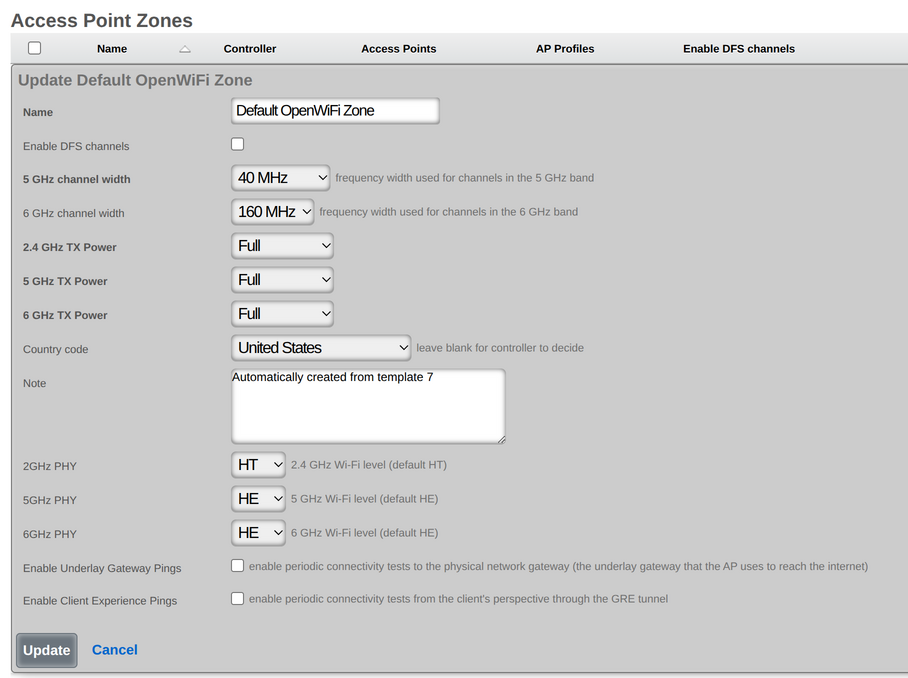
WAP Zones
An entry in the Access Point Zones scaffold defines the configuration common throughout this site.
Entries in the Access Point Zones scaffold are populated automatically after enabling the monitoring checkbox for a supported WLAN controller Infrastructure Device.
Channel Configuration
The Enable DFS channels checkbox instructs the WAPs in this WAP Zone to broadcast at the 5 GHz frequencies that are generally reserved for radars. Disabling the Dynamic Frequency Selection (DFS) prevents the use of 5 GHz channels 52-140.
The 5 GHz Channel Width and 6 GHz Channel Width options configure channel bandwidth for their respective bands. Valid widths include Auto, 20 MHz, 40 MHz, 80 MHz, 80+80 MHz, 160 MHz, and 320 MHz (6 GHz only).
The Channels Disabled fields (channels_disabled_24, channels_disabled_5, channels_disabled_6) allow excluding specific channels from use within each band.
Auto Channel Selection
The Auto Channel Selection fields (per band) control automatic channel assignment: - Disabled: Manual channel assignment only - Background Scanning: Periodic background scans to optimize channels (not available for 6 GHz) - ChannelFly: Dynamic channel hopping based on real-time RF conditions
When ChannelFly is enabled, the Channel Optimization Hour field specifies the hour (0-23) when channel optimization occurs.
Radio Mode Selection
The Radio Mode fields (radio_mode_2g, radio_mode_5g, radio_mode_6g) configure the IEEE Std 802.11 mode per band: - HT: High Throughput (IEEE Std 802.11n) - VHT: Very High Throughput (IEEE Std 802.11ac) - HE: High Efficiency (IEEE Std 802.11ax / Wi-Fi 6) - EHT: Extremely High Throughput (IEEE Std 802.11be / Wi-Fi 7)
Transmit Power Control
The TX Power fields (tx_power_24, tx_power_5, tx_power_6) control transmit power per band, with values ranging from Full (0) to Minimum (-99), expressed in dB reduction from maximum power.
The Auto Cell Sizing checkboxes (per band) enable automatic transmit power adjustment. When enabled, TX Power must be set to Full, and background scanning must be enabled.
The Background Scan checkboxes (per band) enable periodic RF environment scanning for channel and power optimization.
Geographic and Regional Settings
The Country Code field sets the regulatory domain (e.g., US, GB, DE), which determines available channels and power limits.
The Time Zone field configures the zone's local time zone for scheduling and logging.
The Latitude and Longitude fields store the zone's geographic coordinates.
WAP Authentication
The AP Login Name and AP Login Password fields configure credentials for WAP management access. Password requirements vary by controller type.
Advanced Features
The RRM (Radio Resource Management) checkbox enables automatic radio resource optimization.
The Smart Monitor checkbox enables advanced monitoring features.
The Proxy AAA Requests checkbox controls whether authentication requests are proxied through the controller.
The Log Connection Failures checkbox enables logging of client connection failures for troubleshooting.
Client Experience Monitoring
The Client Experience Pings checkbox enables ping-based client connectivity monitoring.
The Underlay Gateway Pings checkbox enables monitoring of the network path to the gateway.
The Client Experience Ping Targets field specifies IP addresses or hostnames for client connectivity testing.
Switch Ports (WAP Connections)
The Switch Ports scaffold on the Wireless page displays a filtered view of switch ports that have an associated WAP. This allows operators to quickly identify which physical switch ports WAPs are connected to across the network infrastructure.
Each entry shows the switch port details along with its associated WAP, providing visibility into the physical network topology of the wireless infrastructure. The Access Point column displays the WAP connected to each port.
The Infrastructure Device column indicates which switch or infrastructure device the port belongs to. The Port field shows the physical port identifier on that device.
Additional fields include Link Speed showing the current negotiated speed, Speed/Duplex for the configured port settings, and Switch Port Profile if a port profile has been assigned.
This view is particularly useful for troubleshooting connectivity issues, verifying WAP installations, and auditing the physical network infrastructure supporting the wireless deployment.
Device Firmwares
The Device Firmwares scaffold manages firmware images for OpenWiFi WAPs. Firmware can be uploaded directly or downloaded from a remote URL for distribution to WAPs.
The Name field provides a descriptive identifier for the firmware image. This is automatically populated from the filename if not specified.
The Version String field displays the firmware version extracted from OpenWiFi firmware packages. This is automatically populated when an OpenWiFi firmware file is processed.
The Firmware Compatibility field specifies the device type this firmware is compatible with (e.g., cig_wf189, edgecore_eap101). This field is used to match firmware to compatible WAPs and is required for OpenWiFi firmware.
The Status column indicates the current state of the firmware record: - init: Initial state when the record is created - process: Firmware is being downloaded or processed - success: Firmware has been successfully downloaded and verified - failed: An error occurred during download or processing
The MD5 and SHA256 fields display the cryptographic hashes of the firmware file, used to verify integrity during distribution to WAPs.
The Default checkbox marks this firmware as the global default for all WAPs that don't have a specific firmware assignment.
The Default for Firmware Compatibility checkbox marks this firmware as the default for WAPs matching the specified firmware compatibility string. Only one firmware per compatibility type can have this enabled.
The Infrastructure Devices association links this firmware to specific WLAN controllers that should be aware of and distribute this firmware.
Firmware can be acquired from the RG Nets firmware distribution server or uploaded manually. When creating a new firmware record, provide either a Remote URL to download from, or upload a file directly. For authenticated downloads, Username and Password fields are available.
Infrastructure Softwares
The Infrastructure Softwares scaffold manages firmware images for infrastructure devices such as switches and PON equipment. This is distinct from the Device Firmwares scaffold which is specific to OpenWiFi WAPs.
The Name field provides a descriptive identifier for the firmware image.
The Device field specifies the type of infrastructure device this firmware is for (e.g., nokiamf_altiplano, edgecoreswitch, catalystiosxeswitch).
The Firmware Type field is used for Nokia PON devices to distinguish between OLT (Optical Line Terminal) and ONT (Optical Network Terminal) firmware. Valid values are: - OLT: Firmware for the central office equipment - ONT: Firmware for customer premises equipment
The Version field displays the firmware version string.
The File Name field shows the name of the firmware file. This is automatically populated from the uploaded file or extracted from the download URL.
The URL field allows specifying a remote URL to download the firmware from. Either a URL or a direct file upload must be provided when creating a new record.
The Status column indicates: - pending: Firmware is queued for download - exists: Firmware file has been downloaded and is available locally
The Model Pattern field is used for Nokia ONT firmware to specify which ONT models this firmware applies to.
The Default Firmware checkbox marks this as the default firmware for automatic upgrades of matching devices.
The Infrastructure Devices association links this firmware to specific infrastructure devices (for OLT firmware).
The Media Converters association links this firmware to specific ONT devices (for ONT firmware).
The Perform Upgrades option, when enabled during save, triggers automatic firmware upgrades on all associated and matching devices.
Infrastructure Device Users
The Infrastructure Device Users scaffold defines user accounts that are pushed to managed infrastructure devices. This allows centralized management of device access credentials across the network infrastructure.
The Username field specifies the login username for the account. This must be unique within each associated infrastructure device and cannot be reserved names like 'admin', 'super', or 'sp-admin'.
The Password field stores the encrypted password for the account. Passwords are securely encrypted in the database.
The Privilege Level field determines the access level for the user: - Read/Write: Full administrative access to the device - Port Read/Write: Access limited to port configuration - Read Only: View-only access to device configuration
The Login Role field specifies an optional role identifier used by some device types for role-based access control.
The Expires At field allows setting an expiration date/time for the account, after which the credentials will no longer be valid.
The Infrastructure Devices association specifies which devices this user account should be pushed to. When the account is created or modified, the credentials are automatically synchronized to all associated devices.
The Note field provides space for administrative comments about the account.
When an Infrastructure Device User is created, modified, or deleted, the rXg automatically triggers a configuration sync to push the updated credentials to all associated infrastructure devices.


