Location
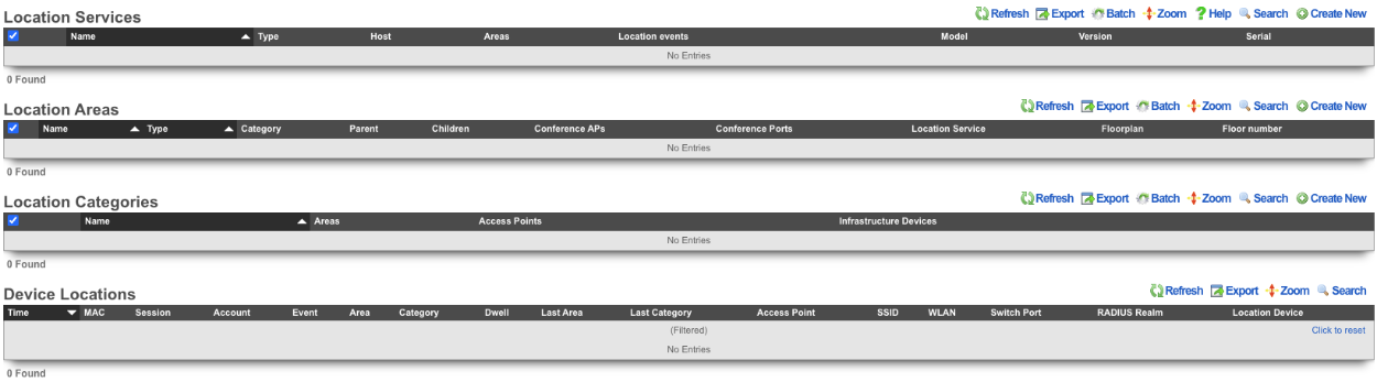
The Location view presents the scaffolds associated with configuring the location services layer of your network.
Location Services
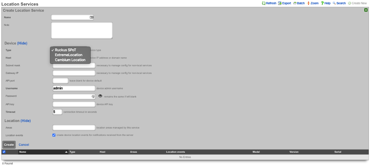
An entry in the Location Services scaffold defines a Location server with which the rXg will use to determine the location of a wireless client.
The name field is an arbitrary string descriptor used only for administrative identification. Choose a name that reflects the purpose of the record. This field has no bearing on the configuration or settings determined by this scaffold.
The note field is a place for the administrator to enter a comment. This field is purely informational and has no bearing on the configuration settings.
The Type field specifies the type of equipment being configured. Choose the appropriate option from the supported device types drop-down menu.
The Host field is the IP address or domain name of the Location device.
The Subnet mask field is used to enter the subnet mask of the network the location device is on.
The Gateway IP field is used to enter the gateway IP address of the location device.
The API port field is used to set the API port, leave blank for device default.
The Username field sets the device admin username.
The Password field sets the device password, note password will remains the same if left blank.
The API key field sets the device API key.
The Timeout field sets the connection timeout in seconds.
The Areas field sets the location areas managed by this service.
The Location events checkbox will create device location events for notifications received from the server if checked.
Location Areas
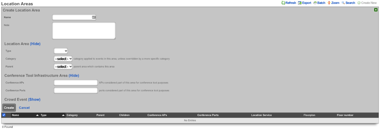
An entry in the Location Areas scaffold allows the Operator of the rXg to define areas that can then be tied to Location Categories.
The Type field is used to determine if the area is a floor or site.
The Category field if set specifies the category applied to events in this area, unless overridden by a more specific category.
The Parent field sets the parent are which contains this area. Example, a site may be a parent to floor.
The Conference APs field allows the Operator to add any APs that should be used for Conferences, this used in conjunction with the conference tool makes it easy to broadcast Conference SSIDs to only the areas where the conference is taking place.
The Conference Ports field allows the Operator to add switch ports that should be used for Conferences.
When configured the Admin Roles field sets the admin roles that will be able to request pending admin transactions from APs in this Location Area.
The Min Gradient and Max Gradient fields allow the operator to override the default heatmap gradiation coloration.
Location Categories
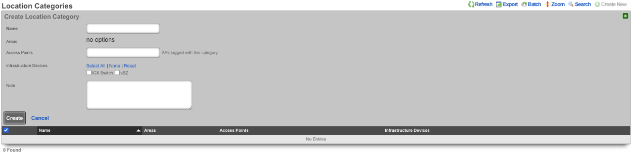
The Areas field allows the Operator of the rXg to assign categories to specific Location Areas , which includes any APs selected when creating the category.
The Access Points field allows the Operator to select specific APs that will be tied to this Location Category.
The Infrastructure Devices field allows the Operator to assign Infrastructure Devices to the Location Category.
Device Locations

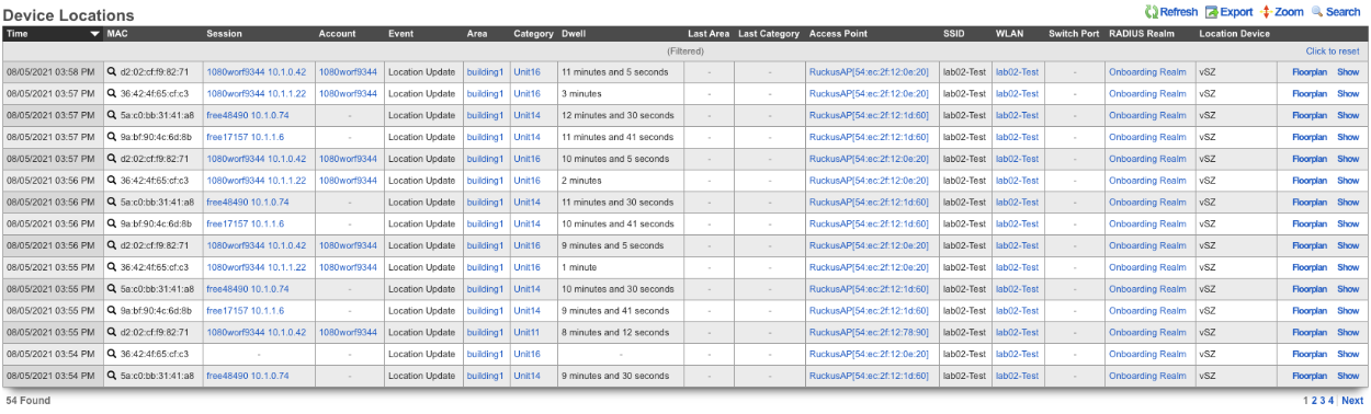
The Device Locations scaffold lists the reported location of devices on the network. The Time entry shows the time the record was created. The MAC entry lists the MAC address of the connected device. The Session entry shows the login session for the device. The Account entry lists the account the device is a member of. The Event field shows the event type for record. The Area field shows the Location Area the record belongs to and the Category field shows the Location Category the record is associated with. The Dwell entry displays the amount of time the device has been in a given area. The Last Area and Last Category entries display the previous are and category the device was associated with. The Access Point entry lists the IP and MAC address the device was connected to at the time the entry was created. The SSID field displays the SSID the client device was connected to. The WLAN entry shows the WLAN on the rXg the client device was associated with. The RADIUS Realm entry shows the radius realm the device authenticated against. The Location Device lists the Infdev device providing the location information.
Example Setup
In this example shows the process of setting up location in a MDU.
- Add floorplan to location area.
- Create regions for AP placement.
- Place AP's into regions.
- Create Location Categories and add AP's.
1. Add floorplan to location area.
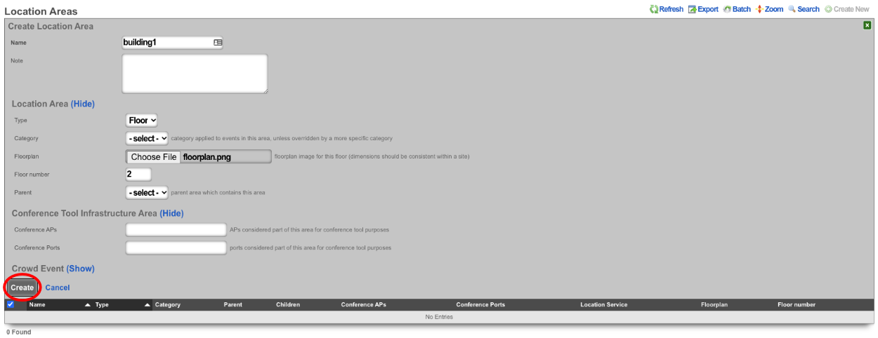
Navigate to **Network::Location** and create a new **Location Area**. The **Name** field is arbitrary, enter a name. Change the **Type** field to **Floor**. Note: by selecting floor it allows the operator to upload a floor plan and this will become the partent for any regions that are created, if **Site** is selected this will be the parent of the floors. Leave **Category** on -select- as there are none to select at this time. For the **Floorplan** field click the Choose File button and select the floorplan image to be used. Set the **Floor number** field to set the floor number. Leave the **Parent** field on -select- and hit the **Create** button.
2. Create regions for AP placement.
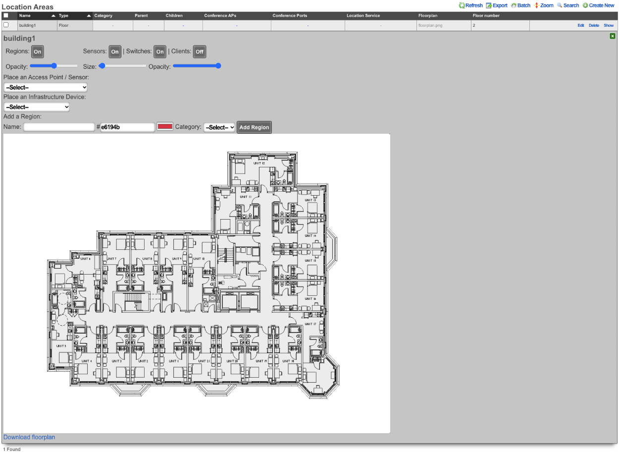
To create regions click on the Floorplan in the **Location Area** scaffold, this will open up the map allowing the placement of APs and Regions.

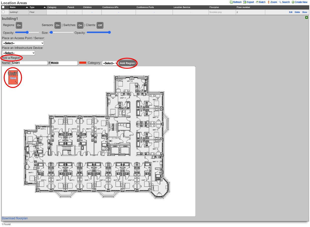
In the **Add a Region** section enter a name for the region, pick a color for the region and then click **Add Region**. This create a region that can be placed on the floorplan. The region can be resized by dragging the bottom right corner.
Drag the region to the desired area on the floor plan, adjust size and click save.
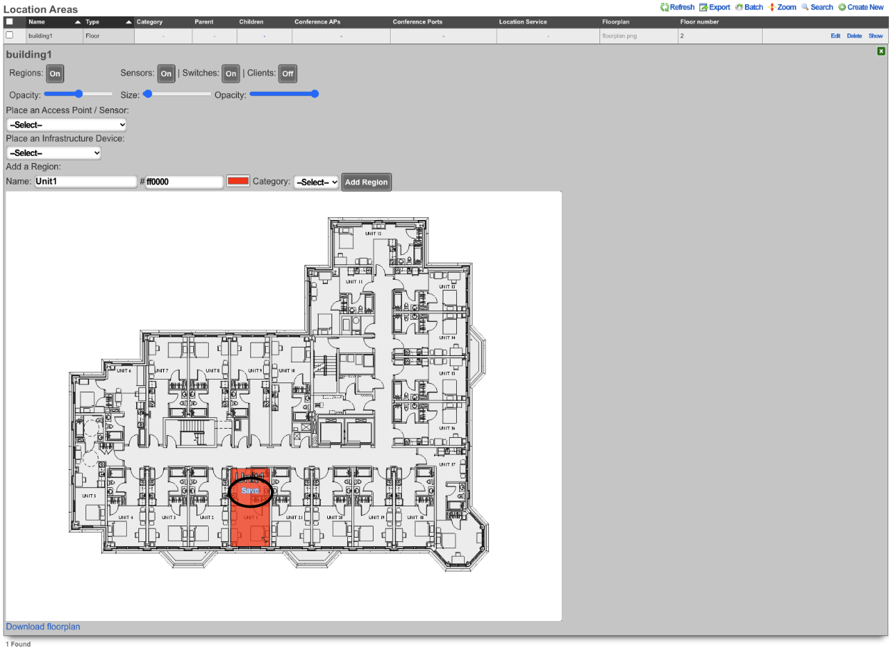
Repeat for each area that needs a region.
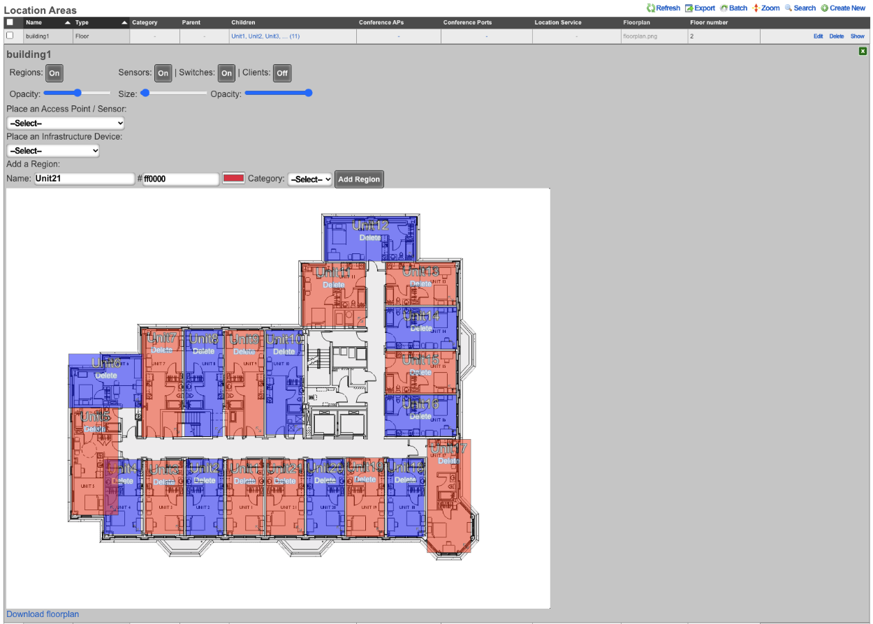
3. Place AP's into regions.
Select an AP from the **Place an Access Point / Senso:** dropdown. Click the **Drag me** button.

This will generate an AP that can be placed on the floor plan, the first AP will go in Unit1.

Drag AP to its placement on the map and click **Save**.
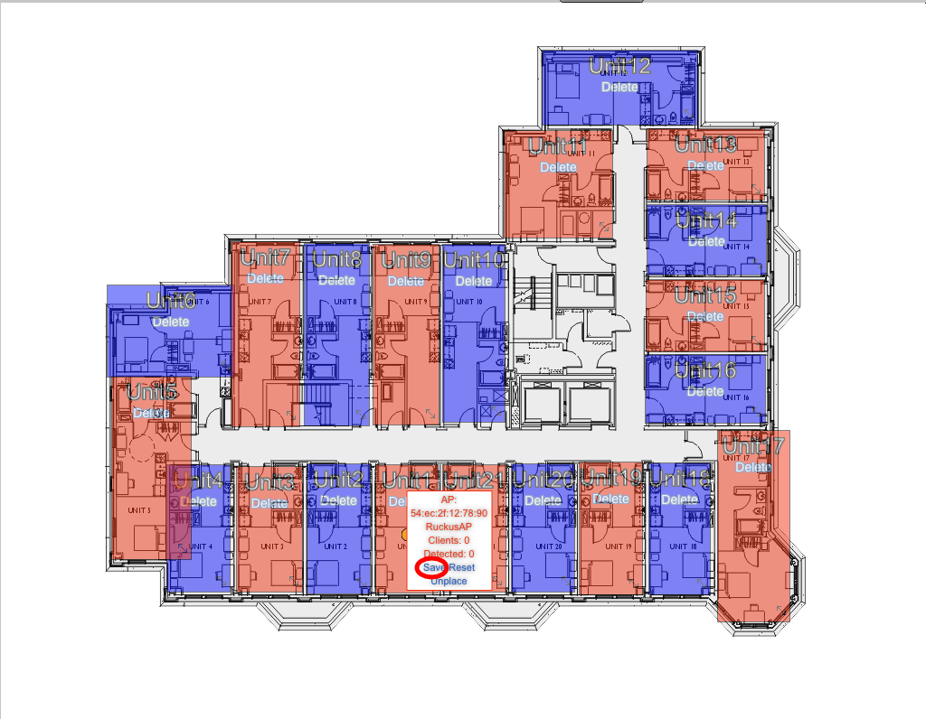
Repeat this step for each AP that is present on the floorplan.
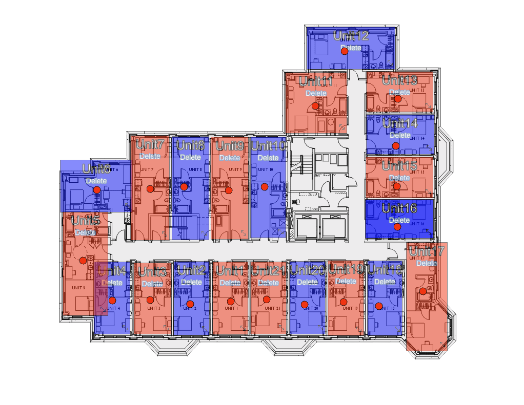
4. Create Location Categories and add AP's.
Create a new **Location Category**.

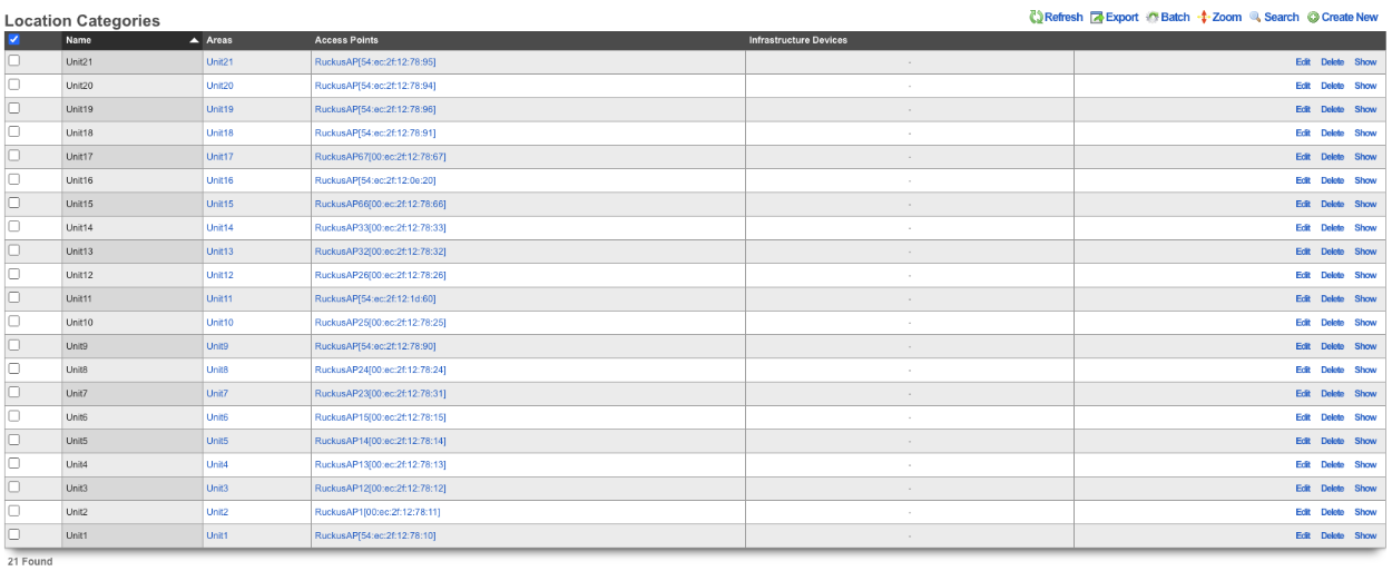
The **Name** field is arbitrary, in this case there will be a **Location Category** created for each unit, the name will reflect the unit. Select the unit for in the **Areas** field. Select the AP or APs from the **Access Points** field. Click **Create**.
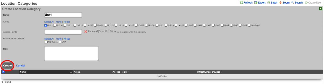
Repeat for each Unit.
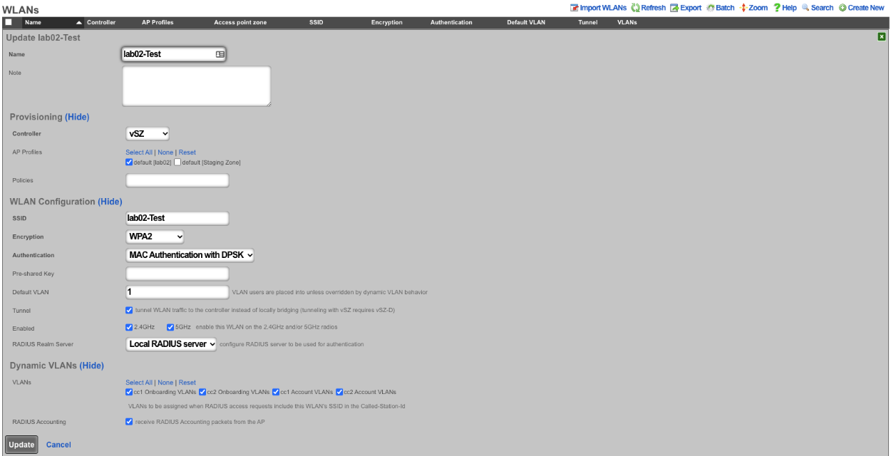
The rXg is now configured to start keeping track of **Device Locations**. In order for this to work at a minimum, radius account packets must be received. The below image shows the **WLAN** settings for the SSID setup for this example. Note: In this example we have control of the wireless infrastructure creating the WLAN pushed all needed settings, without control the WLAN would need to be configured manually on the wireless infrastructure.
The below image shows the information received in the **Device Location** scaffold.
Recalibration
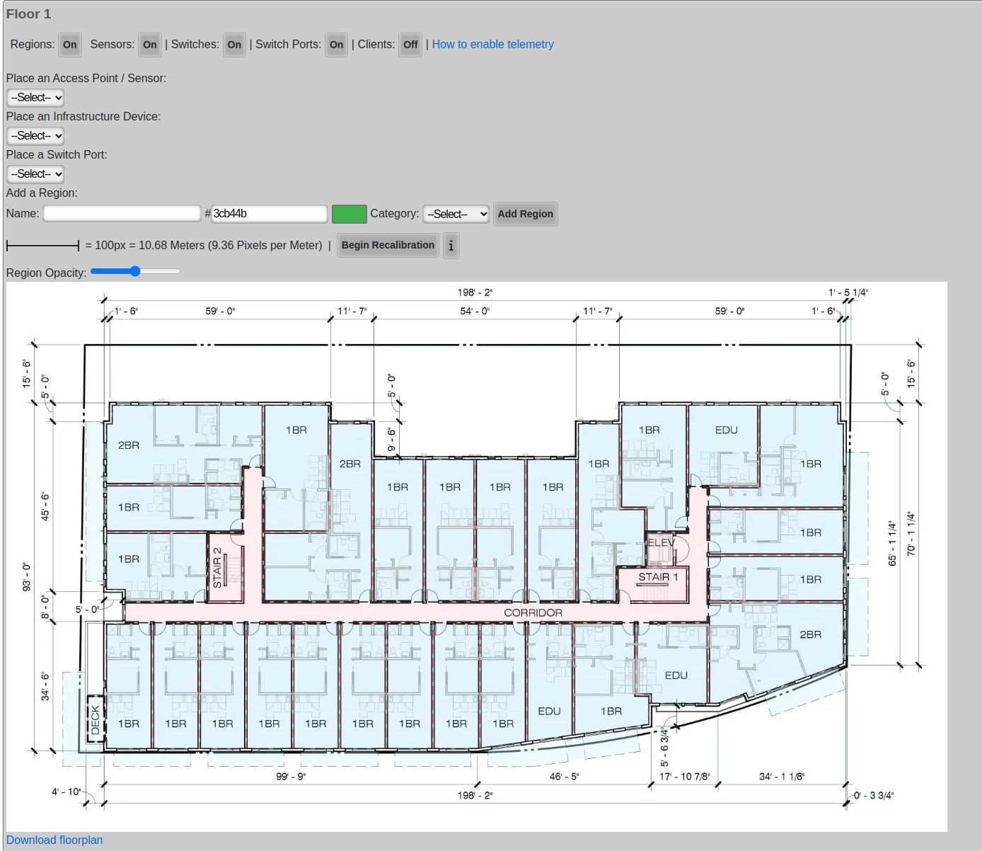
In order for location-aware functionality to work as well as possible, setting the right calibration on your floorplan is essential. In order to begin recalibration, click on 'Begin Recalibration' In the floorplan view:
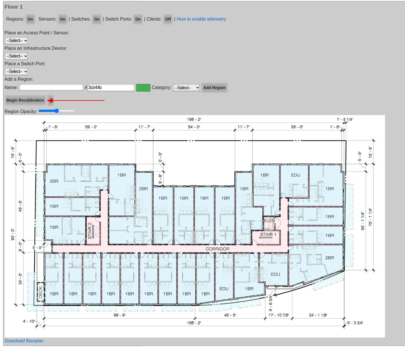
Next, click a point on the map. Often times, a wall or one side of a door frame is a good choice because they are easy to measure, in fact most doors are roughly 1 meter wide.
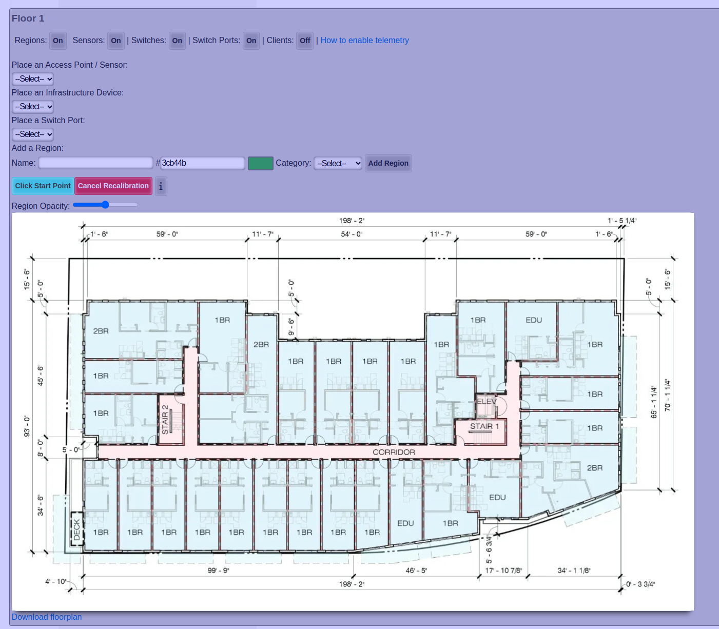
After you clicked your first point, click your second point
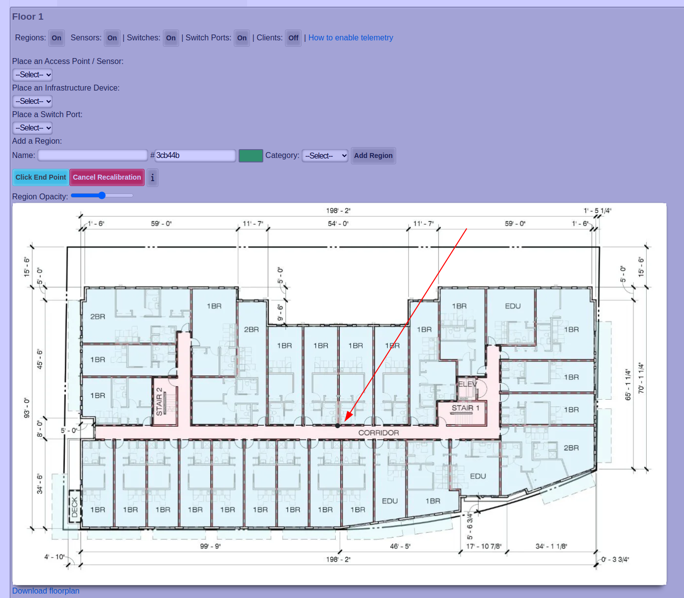
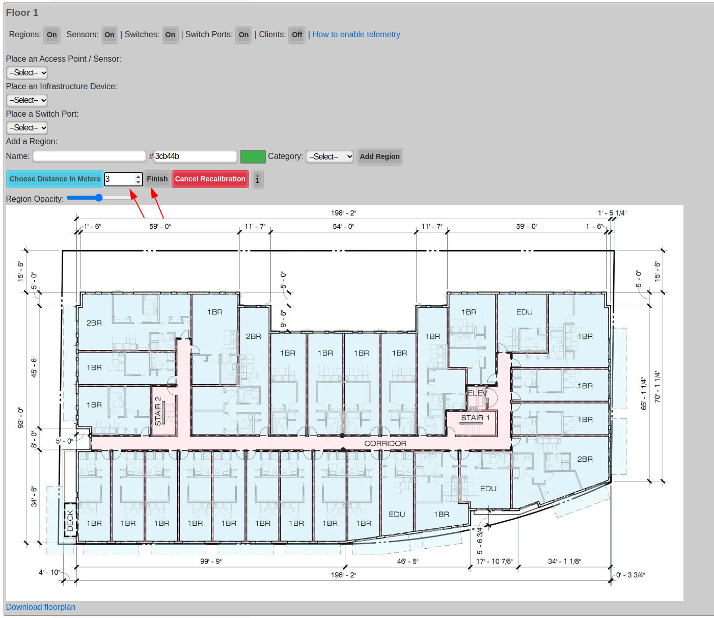
After you clicked your second point, enter the distance between the two points in meters, and click Finish.
Finally just let the floor plan view close on its own and reopen it.
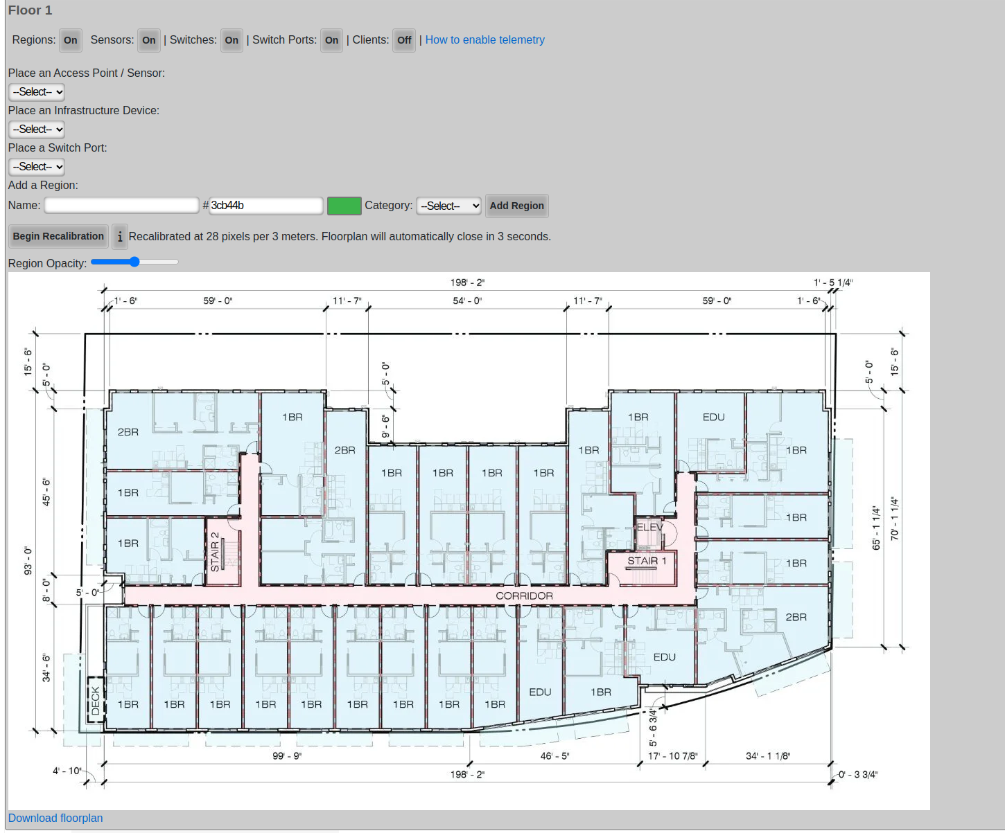
After you re-open the floor plan, the new calibration will be displayed.
RRM
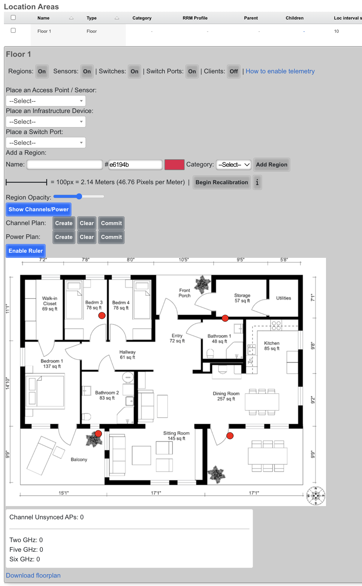
Radio Resource Management (RRM) optimizes wireless network performance by dynamically adjusting radio channels and power levels. The rXg includes the capability to manage this through the Location page in the Location Areas scaffold and the RRM Profiles scaffold.
Channel Planning
Wi-Fi channel planning, a part of Radio Resource Management (RRM), is crucial for optimizing Wi-Fi network performance by strategically assigning channels to access points. Proper channel planning minimizes interference from neighboring Wi-Fi networks and co-channel interference within the same network, leading to a more stable and efficient wireless environment with improved speeds and reliability for all connected devices.
- Ensure all floor Location Areas within the site have floor plans uploaded with Access Points placed on the floor plan. The floor plan should be accurately calibrated to ensure the scale is accurate.
- It's recommended to ensure all floor plans are the same dimensions and each floor plan is positioned so the walls line up between floors. Alternatively, the origin X and Y should be used to nudge the floor plan into the correct location so the rXg knows how much difference there is between floor plans (in meters).
- Populate the Z axis of the origin of each Floor to specify the offset in height (in meters) between the floors compared to the ground.
- Edit a Location Area
- When editing a Location Area for a Floor, the channel planning will occur only for that floor.
- When editing a Location Area for a Site, the channel planning will occur for the entire site.
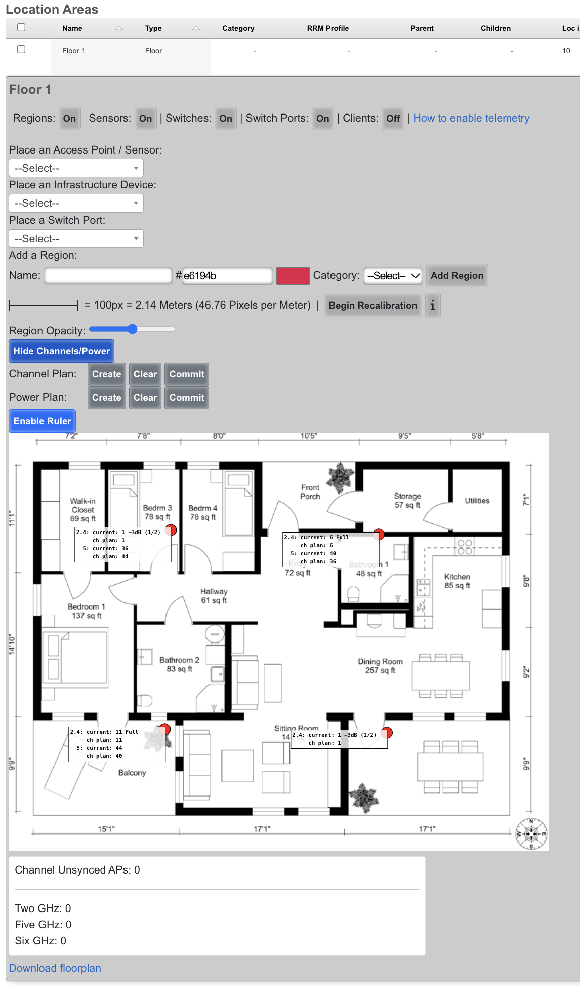
- Next to Channel Plan click Create
Before Channel plan
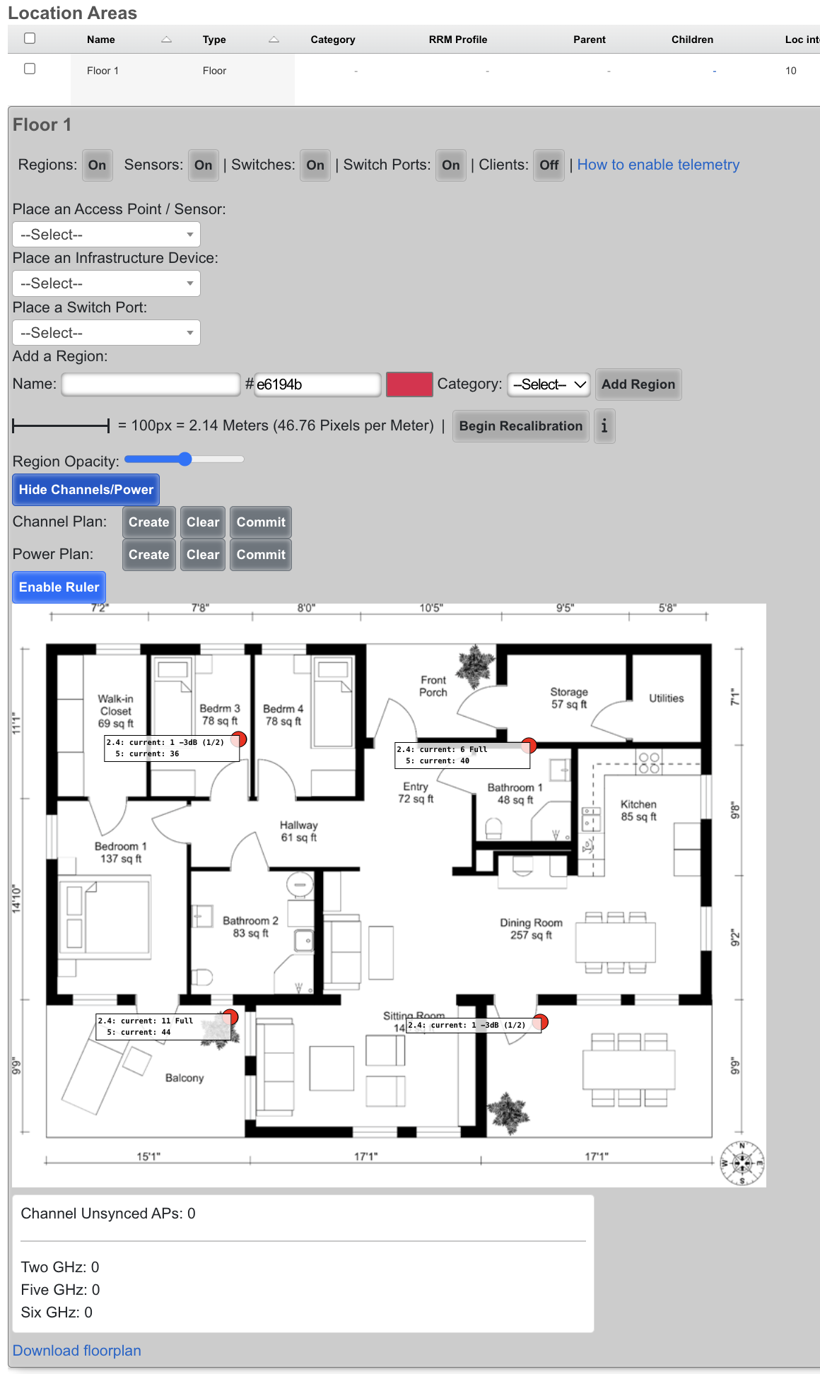
After Channel plan
RRM Profiles
The RRM Profiles scaffold defines reusable sets of radio resource management parameters that control channel planning and heuristic transmit power adjustments. Each Infrastructure Area can be associated with an RRM Profile; areas without an explicit profile assignment will use the profile marked as Default.
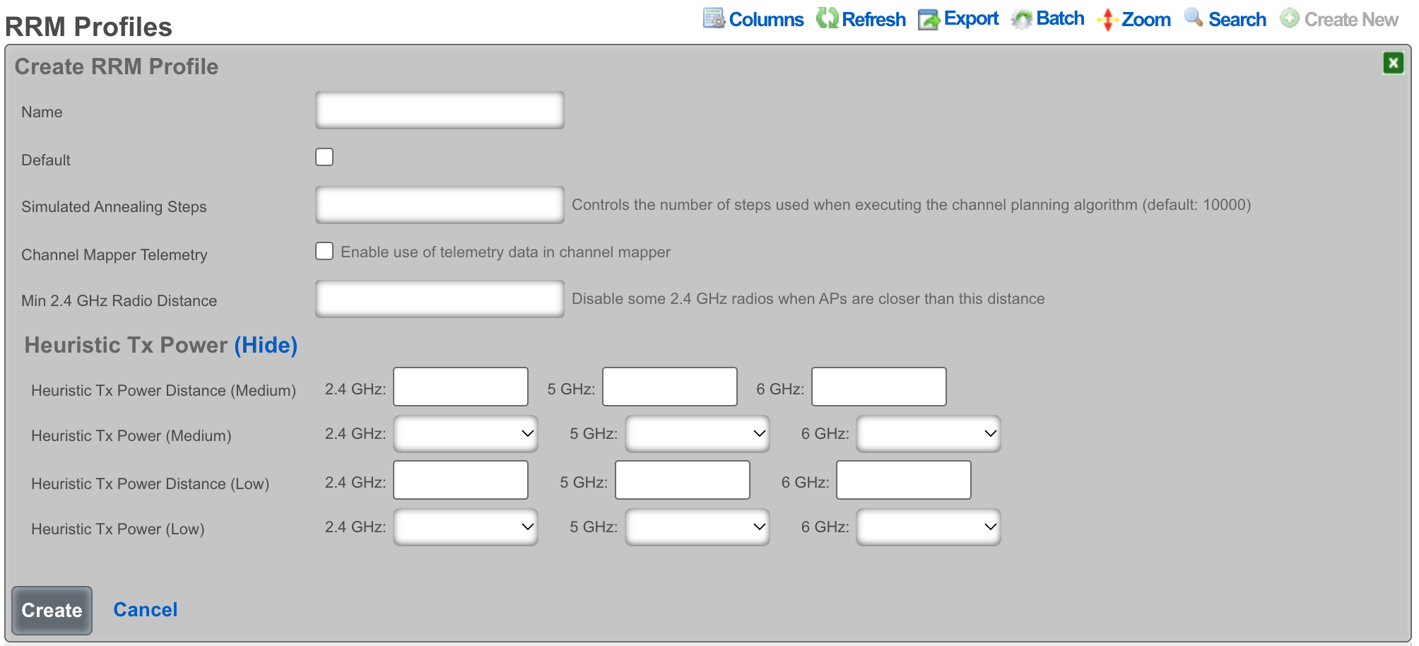
The name field is an arbitrary string descriptor used only for administrative identification. Each RRM Profile must have a unique name.
The default checkbox designates this profile as the system default. Only one profile may be marked as default at a time enabling this on a profile will automatically clear the default flag on any other profile.
Channel Mapper
The Simulated Annealing Steps field controls the number of iterations used when executing the channel planning algorithm. Higher values produce more optimal channel assignments at the cost of additional computation time. The default is 10000.
The Channel Mapper Telemetry checkbox enables the use of telemetry data reported by supported Wireless LAN controllers when computing channel plans. When enabled, the channel mapper incorporates real-world RF measurements from the wireless infrastructure.
The Min 2.4 GHz Radio Distance, Min 5 GHz Radio Distance, and Min 6 GHz Radio Distance fields set per-band distance thresholds (in meters) for disabling radios. When two Access Points are closer together than the specified distance, the rXg may disable one of the radios on that band to reduce co-channel interference. This evaluation is channel-agnostic it considers physical proximity regardless of channel assignment.
Heuristic Tx Power
The Heuristic Tx Power section configures distance-based transmit power reduction on a per-band basis (2.4 GHz, 5 GHz, and 6 GHz). The rXg uses a two-tier power reduction model based on the distance between Access Points:
By Channel When checked for a given band, distance calculations consider only the nearest Access Point on the same channel rather than the nearest AP on the same band. This is useful in deployments where co-channel APs are farther apart than same-band APs on different channels.
Distance (Medium) The distance threshold (in meters) per band at which an AP's transmit power will be reduced to the Medium power setting. When an AP is closer than this distance to another AP, the medium power level is applied.
Power (Medium) The transmit power level applied when an AP is within the Medium distance threshold. Options range from Full power to -18dB (1/64) and Minimum, specified independently for each band.
Distance (Low) The distance threshold (in meters) per band at which an AP's transmit power will be further reduced to the Low power setting. This should typically be set to a shorter distance than the Medium threshold.
Power (Low) The transmit power level applied when an AP is within the Low distance threshold. The same power options are available as for the Medium setting (Full through -18dB and Minimum), specified independently for each band.
Power Level Options
The available transmit power levels for both Medium and Low tiers range from Full (maximum) to Minimum (lowest supported), with intermediate options available in 1dB increments:
| Power Level | Relative Output |
|---|---|
| Full | Maximum transmit power |
| -3dB | 1/2 power |
| -6dB | 1/4 power |
| -9dB | 1/8 power |
| -12dB | 1/16 power |
| -15dB | 1/32 power |
| -18dB | 1/64 power |
| Minimum | Lowest supported transmit power |
Usage
RRM Profiles separate the tuning parameters from the location areas where they are applied. This allows the same set of power and channel planning settings to be shared across multiple floors or sites without duplicating configuration.
When to create an RRM Profile: A single default profile is sufficient for most deployments where all areas have similar AP density and coverage goals. Create additional profiles when different areas require different power behavior for example, a high-density conference hall may need more aggressive power reduction (shorter distances, lower power levels) than a low-density office floor.
Prerequisites: Before RRM Profiles have any effect, the following must be in place: 1. Location Areas configured with floor plans uploaded and calibrated (see Recalibration section above). 2. Access Points placed on the floor plans with accurate positions. 3. At least one RRM Profile must exist and be marked as Default, or explicitly assigned to the Location Area.
How it connects: Each Location Area (Infrastructure Area) has an optional RRM Profile association. When a channel plan or power plan is created from a Location Area, the rXg looks up the area's assigned profile. If none is assigned, it falls back to the profile marked as Default. If no default profile exists, channel and power planning will not have RRM parameters to work with.
Power planning requires at least one complete tier to be configured either a Distance (Medium) and Power (Medium) pair, or a Distance (Low) and Power (Low) pair, for a given band. If neither tier is fully configured for a band, power planning is skipped for that band.