Uplink Control
The uplink control view presents the scaffolds that configure the multiple uplink control mechanism of the rXg.
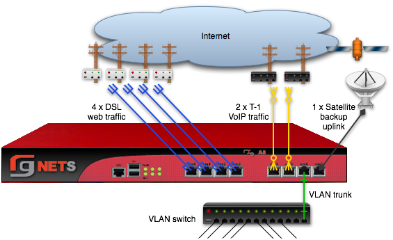
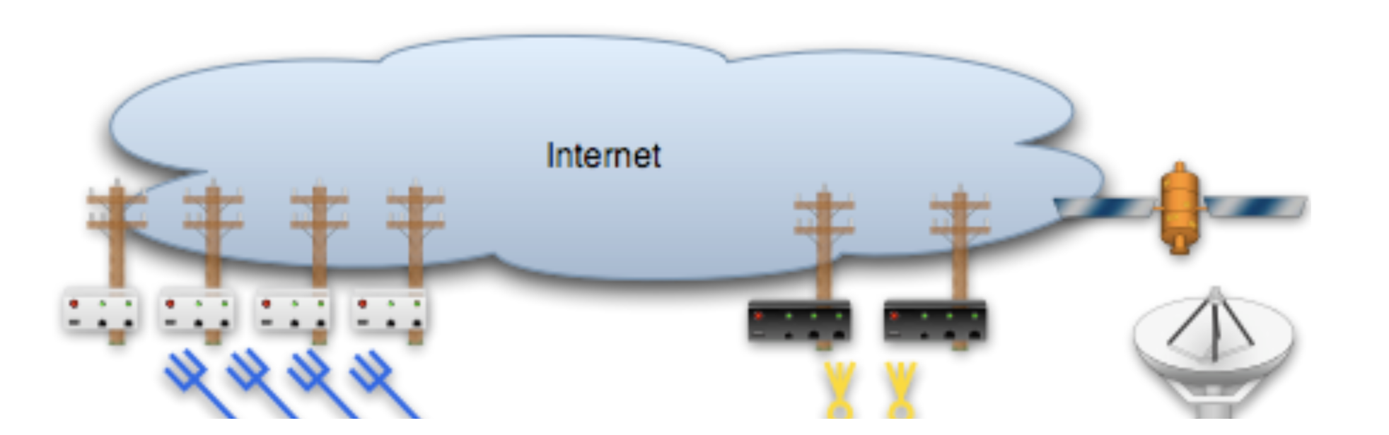
The multiple uplink control mechanism of the rXg enables operators to leverage the capacity and diversity of multiple WAN uplinks without the complexity, operational difficulty and support burden associated with traditional multihoming techniques (e.g., ARIN ASNs, upstream network cooperation and reconfiguration, etc. ). Multiple uplink control provides the operator with four distinct capabilities: bandwidth aggregation, uplink failover, carrier diversity and application affinity.
Bandwidth Aggregation
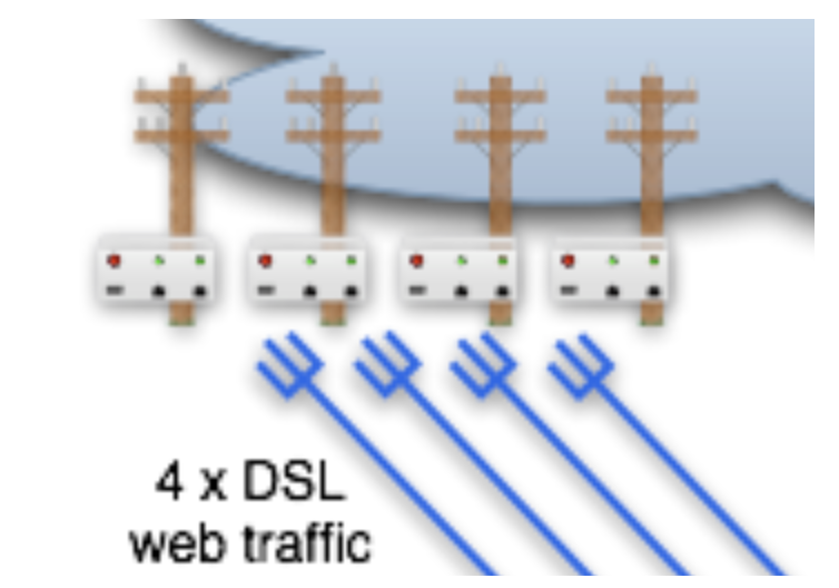
The rXg multiple uplink control mechanism utilizes multiple WAN uplinks as a team. This allows the operator to treat several uplinks as if they were a single high bandwidth uplink. Significant operational cost savings may be achieved through proper employment of this feature. For example, a turn-key rXg can be deployed with multiple uplink control to aggregate seven standard 7.1 Mbps x 768 Kbps ADSLs resulting in a virtual link that is nearly 50 x 5.5 Mbps. The MRCs associated with seven ADSLs is approximately $300, a fraction of the $5000 or more that would be incurred for a 45 Mbps T3.
Aggregating numerous WAN uplinks is also an effective way to scale uplink bandwidth with the end-user population. Since MRCs tend to scale with uplink bandwidth and revenue tends to scale with end-user population, multiple uplink control enables proportional scaling of cost with revenue. In addition, most high-bandwidth leased lines have long deployment lead times. Multiple uplink control enables operators to quickly deploy RGNs with one or two commonly available WAN uplinks (e.g., cable modems and DSLs). The operator may then dynamically increase total available bandwidth by simply adding more WAN uplinks from any ISP of the operator's choosing.
Uplink Failover
The multiple uplink control mechanism enables operators to easily increase the fault tolerance of the network and decrease the dependence of operator on WAN uplink providers. When several WAN uplinks are configured for aggregation, the rXg automatically monitors the health of the WAN uplinks and removes uplinks that have failed from the active pool. If a failed uplink returns to proper operation, the rXg automatically adds the WAN uplink to the active pool.
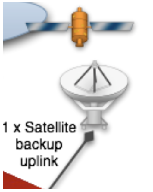
In addition, the rXg supports explicit configuration of backup WAN uplinks. This is useful for situations where a backup uplink that has different characteristics from the one or more primary uplinks. For example, satellite WAN uplink may be designated as an explicit backup uplink that is never used unless all members of a pool of primary DSLs have failed.
Carrier Diversity
The rXg multiple uplink control mechanism operates independently of the upstream carriers. The upstream carriers do not need to make any configuration changes or cooperate with the operator in any way. The multiple uplink control mechanism is so transparent that in most cases upstream carriers do not even know that their link is taking part in a connection pool. The rXg supports multiple uplink control over any number of carriers that are supplying an arbitrary set of uplinks.
With third-party ping targets configured, the rXg multiple uplink control mechanism can determine the health of the uplink carrier's upstream connectivity. This capability combined with WAN uplinks that are being supplied provided by different upstream carriers enables the rXg to provide carrier diversity and failover. Uplinks that are associated with carriers that are having peering difficulty are removed from the active pool.
Application Affinity
The rXg multiple uplink control mechanism can affine specific outgoing traffic to particular WAN uplinks. This capability enables operators to maximize the utilization and capabilities available through a diverse set of WAN uplinks. In a typical configuration, most traffic is sent across one set of WAN uplinks while traffic with special needs are sent through a different set of WAN uplinks.
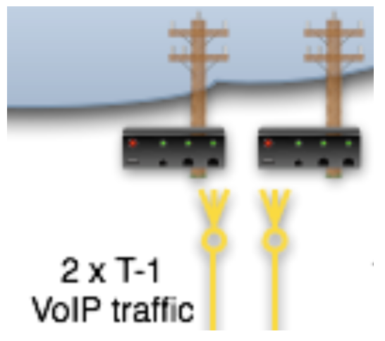
For example, an operator that has a single T-1 and three ADSLs may choose to affine all VoIP traffic to the T-1. This allows the VoIP to be delivered at a lower latency that will make a noticeable difference in call quality. Link affinity may also be used in conjunction with application forwards and DNS mappings to reserve certain WAN uplinks for public facing services.
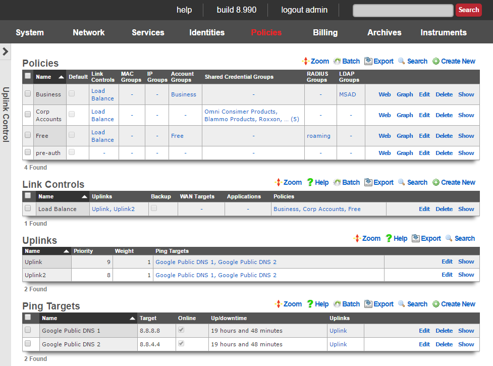
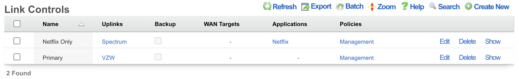
Uplink Control
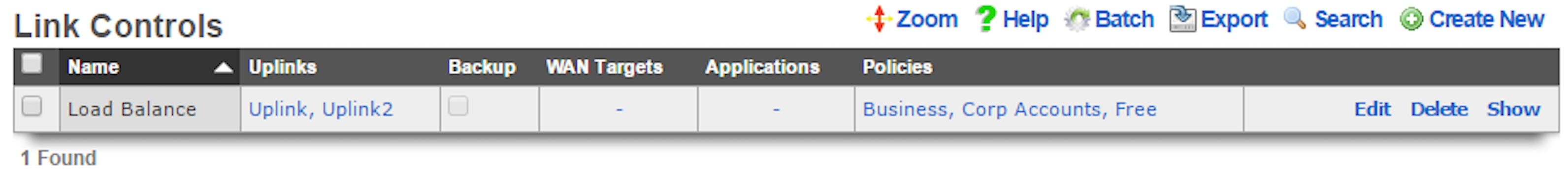
Uplink Control records define the configuration of the multiple rXg uplink control mechanism.
The name field is an arbitrary string descriptor used only for administrative identification. Choose a name that reflects the purpose of the record. This field has no bearing on the configuration or settings determined by this scaffold.
The uplinks field determines which WAN uplinks will take part in the multiple uplink control policy configured by this record. When more than one uplink is set, the rXg will automatically load balance the links. The distribution of load across the selected uplinks is determined by the weight field of the WAN uplink records.
The backup checkbox configures the Uplink Control group configured by this record to remain inactive unless all other links associated with an Uplink Control record that is not designated as a backup have failed. At least two Uplink Control records (one designated as backup and one that is not) must be associated with the same policy in order for this field to have any effect.
The WAN targets field limits the effect of the Uplink Control defined by this record to traffic that is originating from or destined to the IP addresses or DNS names listed in the selected WAN targets. By default, an Uplink Control affects all traffic originating from and destined to the members of all groups associated through the linked policies. Setting a WAN target causes the Uplink Control to limit the breadth of the rule to the specified hosts.
The applications field configures the kinds of packets that will be link controlled as a result of this record. Selecting multiple application groups applies this rule to all of the selected applications (logical or). By default, all types of packets that match the chosen policy and WAN targets are link controlled. Selecting one or more applications reduces the breadth of the rule configured by this record to the packets classified as being part of the chosen applications.
The policy field relates this record to a set of groups through a policy record.
The note field is a place for the administrator to enter a comment. This field is purely informational and has no bearing on the configuration settings.
Validation Requirements
When creating or updating an Uplink Control, the following validation rules apply:
- Each selected uplink must have at least 2 ping targets configured. This ensures reliable health monitoring with redundancy.
- If WAN Targets or Applications are specified, the associated policies must have Traffic Shaping records matching those filters.
- At least one uplink must be selected.
Uplink Control Behaviors
Single Uplink in Group: All associated policy traffic uses that uplink. Simple assignment with no load balancing.
Multiple Uplinks in Group: Traffic is distributed by weight ratio across all online uplinks. Provides bandwidth aggregation.
Backup Flag Enabled: The Uplink Control remains inactive until all non-backup Uplink Controls for the same policy have no online uplinks. Use for explicit failover without aggregation.
Uplinks
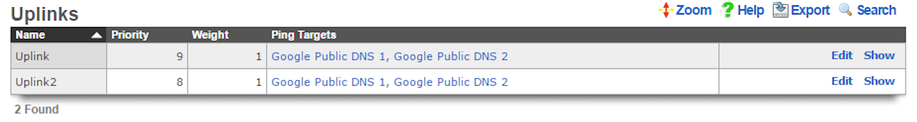
This scaffold brings visibility to the columns of the uplinks scaffold that are relevant for multiple uplink control. Since uplinks are defined via the uplinks scaffold in the WAN view of the Network subsystem, this scaffold is limited to editing settings relevant to multiple uplink control.
The name field is an arbitrary string descriptor used only for administrative identification. Choose a name that reflects the purpose of the record. This field has no bearing on the configuration or settings determined by this scaffold.
The priority field determines the order of precedence during failover in a multiple uplink control scenario. When only one uplink is configured, this field has no effect as there is no uplink to failover to. When multiple uplinks are configured and connection aggregation is enabled, a failure of a link will cause another member of the pool to forward all traffic. If aggregation is not enabled, or all uplinks within a pool have failed, then the uplink with the highest priority amongst all of the remaining uplinks will be used to forward the traffic.
The weight field is used to determine how load is distributed across a set of uplinks that have been grouped together into a single Uplink Control. If all uplinks in the Uplink Control have the same weight, the end-users will be assigned to the uplinks in a simple round-robin (uniformly distributed) fashion. If the uplinks have different weights, end-users are assigned to uplinks in a distribution that uses the uplink weight as a ratio with respect to the sum total of the weights. For example, if an Uplink Control has two uplinks associated with it and the weights of the uplinks are 2 and 5, 28% (2/7) of the end-users will be assigned to the first link and 72% (5/7) of the end-users will be assigned to the second link.
Where to configure: Weight is configured via Policies :: Uplink Control Uplinks (a separate section on the same page). Edit a specific uplink from this section to adjust its weight. Note: Weight is a global property of the uplink, not per-Uplink Control.
The ping targets field associates ping targets with this uplink. Ping targets are used to determine the health of the uplink. When all of the ping targets associated with the given uplink fail, i.e., are not reachable via an ICMP ping, the uplink is marked as down until at least one of the ping targets recovers and responds to the ICMP pings.
The note field is a place for the administrator to enter a comment. This field is purely informational and has no bearing on the configuration settings.
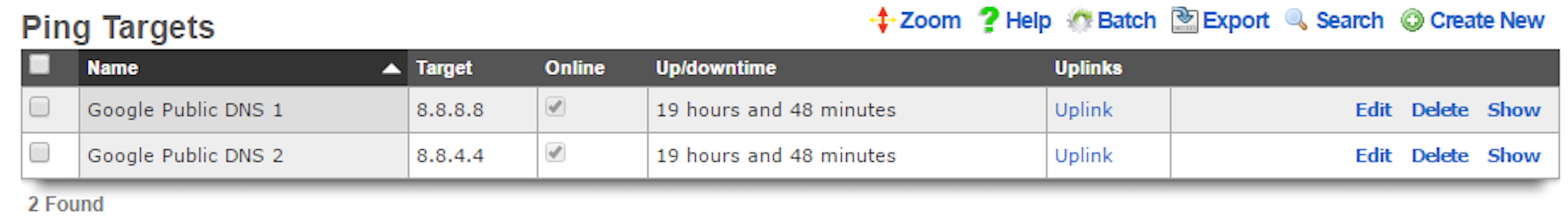
Ping Targets
The ping targets scaffold configures the third-party ping targets that are used to determine availability of various system services, including the uplink availability. Each uplink should have more than one ping target associated with it in order to properly determine uplink health. Individual ping targets may be associated with instances of DNS server or uplink interfaces, as shown below.
The name field is an arbitrary string descriptor used only for administrative identification. Choose a name that reflects the purpose of the record. This field has no bearing on the configuration or settings determined by this scaffold.
The target is the IP address or hostname of the device that is to be sent an ICMP ping. For reliable uplink monitoring, use external targets such as 8.8.8.8 (Google), 1.1.1.1 (Cloudflare), or 9.9.9.9 (Quad9) rather than ISP infrastructure.
The timeout is the number of seconds (maximum 10) that the rXg will wait for a response from the target to an ICMP ping request. Default is 3.0 seconds.
The attempts is the number of times (1-12) an ICMP ping will be tried per check cycle before evaluating the result. Default is 6 attempts.
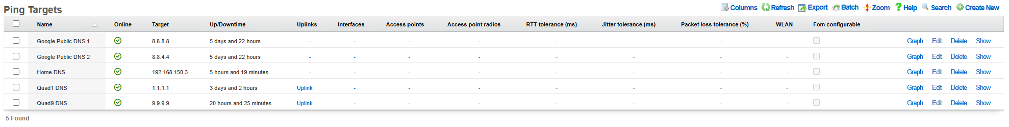
Link Quality Thresholds
The following threshold fields allow fine-grained control over uplink health determination. When any threshold is exceeded, the uplink may be marked offline.
The RTT tolerance field specifies the maximum acceptable round-trip time in milliseconds. If the average RTT exceeds this value, the ping target is considered unhealthy.
The jitter tolerance field specifies the maximum acceptable variation in round-trip time in milliseconds. High jitter indicates unstable connectivity and may affect real-time applications like VoIP.
The packet loss tolerance field specifies the maximum acceptable packet loss percentage (0-100). For example, setting this to 20 allows up to 20% packet loss before the target is considered unhealthy.
These thresholds enable detection of degraded links that are technically reachable but performing poorly. This is especially useful for identifying ISP congestion or routing issues that wouldn't be detected by simple reachability tests.
The uplinks field associates this ping target with one or more uplinks for health monitoring.
The interfaces field associates this ping target with one or more interfaces for monitoring.
The check span checkbox enables pinging from all span IPs associated with the interface.
The note field is a place for the administrator to enter a comment. This field is purely informational and has no bearing on the configuration settings.
Simple Example Configurations
A minimum of two Uplinks must be configured to enable multiple uplink control functionality. Physically connect two distinct Internet connections to the rXg. Use the Network :: WAN view to create the appropriate Network Address objects as well as the associated Uplink objects. Ensure that reasonable Ping Targets are associated with each Uplink object.
Uplink Control is defined by Policy. The operator must identify the people and/or devices to which they wish to apply Uplink Control. For the purposes of demonstration the creation of a single IP Group to cover the management Network Address is sufficient. Most production environments will have Account Groups representing tiers of service. In either case, Policy objects connected to Uplink Control object(s) determine the behavior.
Bandwidth Aggregation and Failover
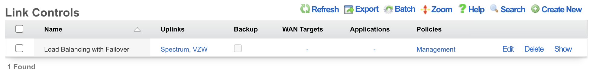
Bandwidth aggregation is configured by associating a single Uplink Control record to a Policy. The Uplink Control record must have multiple Uplinks selected to enable aggregation. If a single link in the aggregation pool fails all traffic will be automatically moved over to the remaining operational uplink(s).
Uplink Failover Only
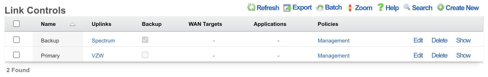
Uplink failover without aggregation is configured by associating at least two Uplink Control records to a Policy. The Uplink Control record for the primary uplink must have the Backup checkbox cleared and the appropriate Uplink associated. The Uplink Control record for the failover uplink must have the Backup checkbox enabled and the appropriate Uplink associated. All traffic will flow over the primary Uplink until there is a failure. No traffic will pass over the secondary Uplink until primary uplink failure occurs.
Application Affinity
Application affinity is configured by associating at least two Uplink Control records to a Policy. The Uplink Control record for the primary Uplink should have the appropriate Uplink associated. The Uplink Control record for the specific traffic designed to go over the secondary uplink should have the appropriate Application and/or WAN Target configured as well as the appropriate Uplink associated.
Policy-Based Routing
Policy-based routing connects user and device groups to Uplink Controls, enabling differentiated routing based on identity, application, or destination.
Traffic Flow
The path from device to uplink follows this sequence:
Device Group Policy Uplink Control Uplink(s)
- Device connects and is identified (IP, MAC, credentials)
- System determines group(s) the device belongs to based on identity
- Group's associated policy determines enforcement rules
- Policy's Uplink Control(s) specify which uplink(s) to use
- Traffic is routed through the selected uplink(s)
Multiple Uplink Controls per Policy
A single policy can have multiple Uplink Controls with different routing behaviors:
| Uplink Control | WAN Targets | Applications | Uplinks | Effect |
|---|---|---|---|---|
| VoIP Traffic | - | SIP, RTP | T1 Line | VoIP uses low-latency link |
| Video Streaming | Netflix, YouTube IPs | - | Cable Modem | Streaming uses high-bandwidth link |
| Default | - | - | All Uplinks | Everything else load-balanced |
Traffic is matched against Uplink Controls in order of specificity. More specific rules (with WAN Targets or Applications defined) take precedence over general rules.
Viewing Current Uplink Assignments
To see which uplink each device is currently using:
Navigate to Policies :: Uplink Assignments
This shows: - Device IP and MAC address - Currently assigned uplink - Associated policy - Uplink Control rule that made the assignment
Quick Reference
Priority and Weight
| Setting | Default | Range | Purpose |
|---|---|---|---|
| Priority | Auto-assigned | 1-9 | Failover precedence (higher = preferred) |
| Weight | 1 | 1-9 | Traffic distribution ratio in aggregation |
Weight Distribution Examples
| Uplink A Weight | Uplink B Weight | Traffic to A | Traffic to B |
|---|---|---|---|
| 1 | 1 | 50% | 50% |
| 2 | 5 | 28.6% | 71.4% |
| 1 | 9 | 10% | 90% |
| 3 | 1 | 75% | 25% |
Distribution is per-device/session, not per-packet, ensuring session continuity.
Minimum Requirements
| Component | Requirement |
|---|---|
| Uplinks for failover | 2 minimum |
| Ping targets per uplink | 2 minimum |
| Uplink Control records for backup mode | 2 (one primary, one with backup flag) |
Health Check Timing
The PingMonitor service checks all configured ping targets approximately every 37 seconds. When all ping targets for an uplink fail, the uplink is marked offline and traffic is redistributed to remaining healthy uplinks.
Online Status
Each uplink maintains an online/offline status:
- Online: Uplink is healthy (at least one ping target responding within thresholds)
- Offline: All ping targets have failed or thresholds exceeded
The highest-priority online uplink becomes the default route when Uplink Controls are not configured.


