NAT
The NAT view presents the scaffolds that configure settings to modify the network address translation mechanisms of the rXg.
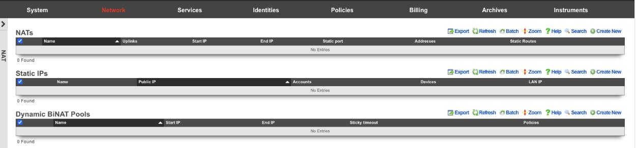 The NAT view with scaffolds for configuring network address translation
NAT
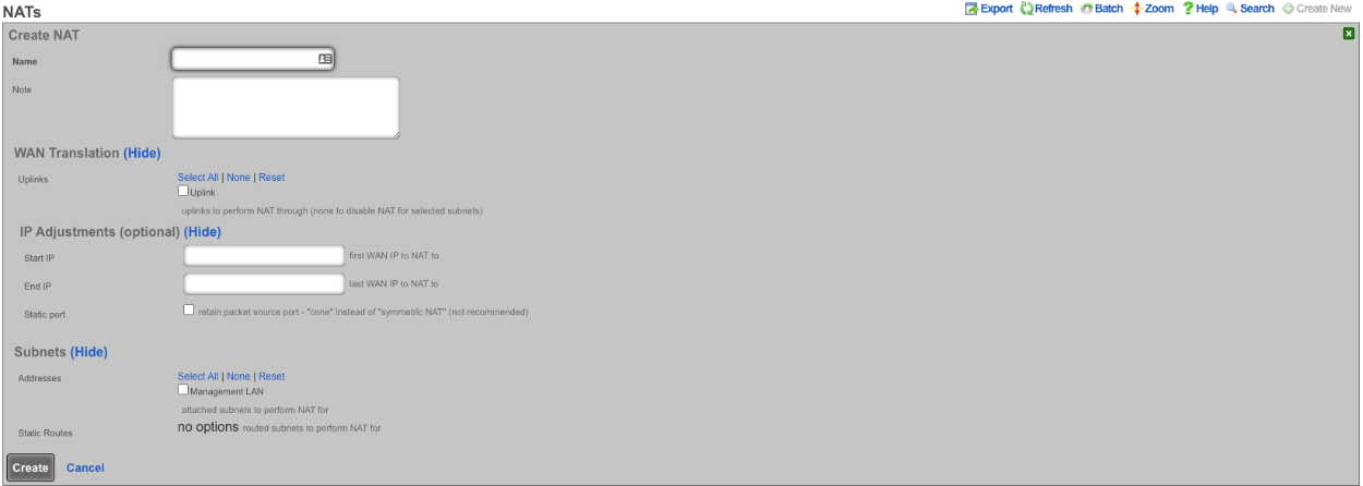 NAT scaffold displaying configured NAT rules
Entries in the NAT scaffold configure network address translation between LAN subnets and WAN addresses.
NAT Pool Fields
Note on Terminology: A "NAT pool" refers to a range of public IP addresses used for Port Address Translation (PAT), also known as NAT overload or many-to-one NAT. When Start IP and End IP are configured, multiple LAN devices share these public addresses by using different source ports for each connection.
The name field is an arbitrary string descriptor used only for administrative identification. Choose a name that reflects the purpose of the record. This field has no bearing on the configuration or settings determined by this scaffold.
The addresses and static routes field specify the source LAN subnets for which network address translation will be enabled by this record.
The uplinks field specifies the WAN address(es) that will be used as the source address for outbound traffic from the selected LAN subnets after NAT translation.
The Reverse NAT field specifies that traffic originating from the rXg itself (not LAN clients) will be NAT'd to the first IP of the selected Addresses. This option is primarily used when the upstream ISP assigns a private IP via DHCP but routes a block of public IPs to that private address. In this scenario, the public IP block is configured as a Network Address on the WAN interface, and Reverse NAT ensures outbound traffic from the rXg uses the first public IP from that routed block rather than the private DHCP-assigned uplink IP.
The Start IP field determines the first IP address of a range of WAN addresses that will be used as a NAT pool for Port Address Translation (PAT). When configured, outbound connections from selected LAN subnets will be translated to addresses within this pool, distributing the load across multiple public IPs. The IP must fall within a WAN address subnet associated with the selected uplink.
The End IP field specifies the last IP address in the range of WAN addresses that will be used for the NAT pool. Together with Start IP, this defines the pool of public addresses available for PAT. The IP must fall within the same WAN address subnet as the Start IP.
The Static Port field, when enabled, preserves the original source port when performing NAT translation. When enabled, if a client uses source port 5060, the translated connection will also use port 5060 (if available). This is often beneficial for: - SIP-based VoIP systems that expect consistent port mappings - Certain gaming consoles and peer-to-peer applications - Applications that embed port numbers in their protocol messages
When disabled (the default), the rXg may rewrite source ports as needed to avoid conflicts, which maximizes port utilization efficiency.
Validation Rules for NAT Pools: - Both Start IP and End IP must be valid IPv4 addresses within a configured WAN subnet - Start IP and End IP must belong to the same WAN address subnet - Start IP must be less than or equal to End IP - The IP range cannot overlap with other NAT pools of the same type - At least one uplink must be selected when specifying a Start IP / End IP range - Selected Addresses and Static Routes must be LAN subnets (not WAN) - Reverse NAT is mutually exclusive with Start IP/End IP, Static Port, and Static Routes fields
Best Practices: - Avoid overlapping IP ranges with Dynamic BiNAT pools to prevent unexpected behavior - Avoid including the uplink's gateway IP address in the NAT pool range - For clarity, consider selecting exactly one uplink per NAT pool when using Start IP / End IP ranges
The note field is a place for the administrator to enter a comment. This field is purely informational and has no bearing on the configuration settings.
If no records are present in the NAT scaffold, the rXg will automatically enable NAT from subnets that are configured with RFC 1918 specified private addresses.
NAT Monitoring
The rXg provides several instruments for monitoring NAT activity on the Instruments :: NAT Assignments view:
- NAT Assignments - View real-time NAT mappings showing which private IPs are translated to which public IPs
- NAT Pool Stats - Monitor utilization statistics across configured NAT pools
Example NAT Pool Deployment
This example demonstrates configuring a NAT pool using a /27 block of public IP addresses (30 usable IPs) for Port Address Translation (PAT). This configuration allows thousands of LAN devices to share the pool of public IPs.
Prerequisites
Before configuring a NAT pool, ensure you have:
- A configured Uplink with WAN connectivity
- A block of public IP addresses from your ISP (routed to your primary WAN IP or directly on the WAN segment)
- LAN subnets (Addresses) that need NAT translation
Step 1: Configure the WAN Address Block
Navigate to Network :: WAN :: Network Addresses and create a new Address for the NAT pool block.
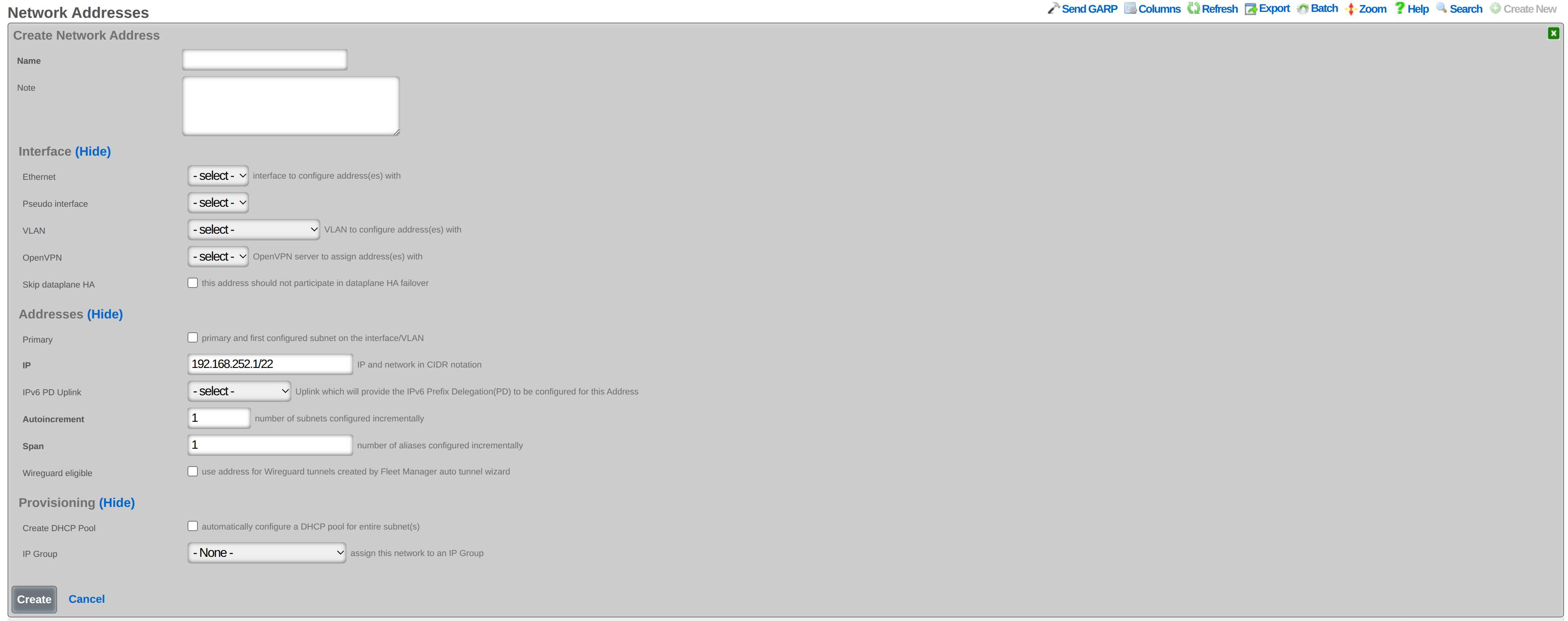 Creating a WAN Address for the NAT pool IP block
Configure the following:
- Name: A descriptive name (e.g., PRIMARY-NAT-WAN-IP-POOL)
- CIDR: The IP block in CIDR notation (e.g., 203.0.113.32/27)
- Interface: Select the same interface your Uplink uses
- Span: Set to the number of consecutive IPs from the block that should be consumed (e.g., 30 to consume an entire /27 block)
- Primary: Leave unchecked (the primary WAN IP is already configured)
The Address must be associated with a WAN interface (the same interface used by your Uplink) to be recognized as a valid WAN address for NAT pools. The Span determines how many consecutive IPs from the block are assigned to the rXg and available for the NAT pool.
Step 2: Create the NAT Pool Rule
Navigate to Network :: NAT and create a new NAT entry.
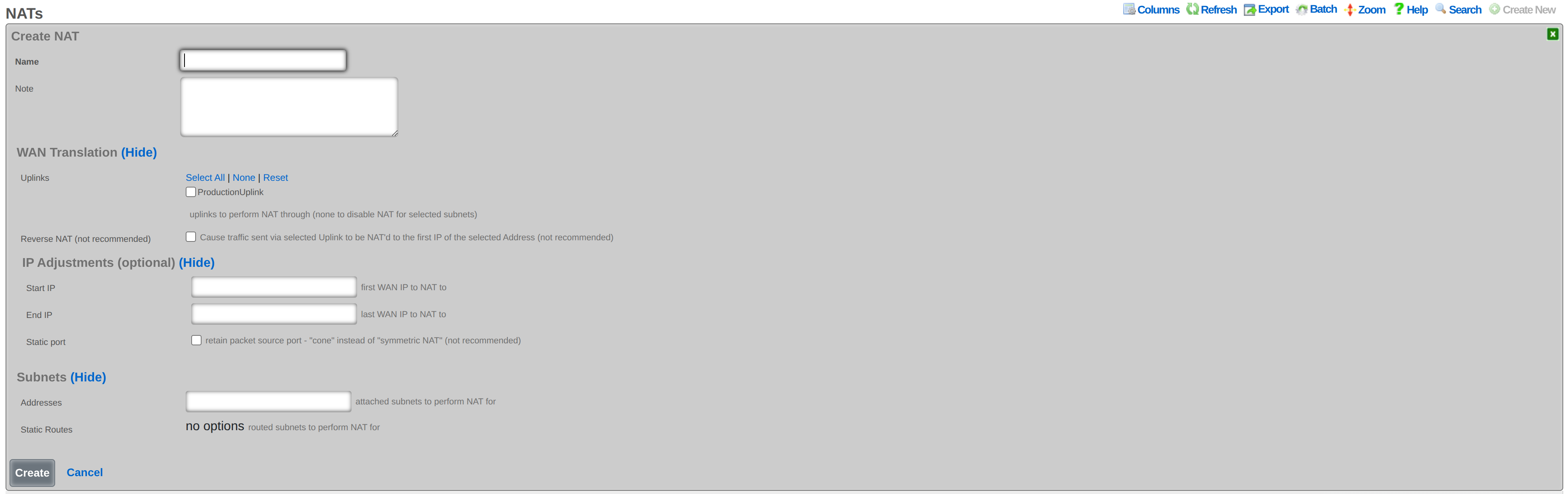 Creating a NAT pool rule with IP range and LAN subnet selection
Configure the following:
- Name: A descriptive name (e.g., Primary-NAT-Pool)
- Uplinks: Select the WAN uplink(s) to use for this NAT pool (at least one required)
- Start IP: The first usable IP in your range (e.g., 203.0.113.33)
- End IP: The last usable IP in your range (e.g., 203.0.113.62)
- Addresses: Select your LAN subnet(s) that should use this NAT pool
Important: When configuring Start IP and End IP, at least one Uplink must be selected. The IP range must fall within a WAN Address subnet associated with the selected Uplink's interface.
Step 3: Verify the Configuration
After creating the NAT pool:
- Navigate to Network :: NAT and confirm your NAT pool entry appears with the correct Start IP and End IP values
- Navigate to Instruments :: NAT Assignments to view real-time NAT mappings as LAN devices generate traffic
- Navigate to Instruments :: NAT Pool Stats to monitor pool utilization
Capacity Planning
With a /27 block (30 usable IPs) and standard PAT:
| Metric | Value | Notes |
|---|---|---|
| Public IPs | 30 | Usable IPs in a /27 (32 minus network and broadcast) |
| Ports per IP | 64,512 | Full port range (65,536) excluding reserved ports 0-1023 |
| Theoretical max connections | 1,935,360 | 30 IPs 64,512 ports |
| Practical device support | Thousands | Each device typically uses 100-500 ports |
Each LAN device typically uses 100-500 ports for normal browsing, so 30 IPs can support several thousand simultaneous users. Heavy users (streaming, gaming, many browser tabs) may use 1,000+ ports.
Splitting the Pool
If you need to reserve some IPs for other purposes (e.g., future BiNAT or Static IP assignments), configure a smaller range:
| Purpose | Range | Count |
|---|---|---|
| NAT Pool | 203.0.113.33 - 203.0.113.50 |
18 IPs |
| Reserved for BiNAT/Static | 203.0.113.51 - 203.0.113.62 |
12 IPs |
Multiple LAN Subnets
You can NAT multiple LAN subnets through the same pool by selecting multiple entries in the Addresses field. All selected subnets will share the NAT pool, with connections distributed across the available public IPs.
NAT Pool Troubleshooting
Error: "does not fall within any configured WAN subnets"
Cause: The Start IP or End IP is not within a WAN Address subnet associated with the selected Uplink's interface.
Solution:
1. Navigate to Network :: Addresses
2. Verify your NAT pool block (e.g., 203.0.113.32/27) exists
3. Ensure the Address is assigned to the same Interface used by your Uplink
4. If the Address doesn't exist, create it with the correct Interface association
Error: "conflicts with existing pool"
Cause: The IP range overlaps with another NAT pool or Dynamic BiNAT pool.
Solution: 1. Navigate to Network :: NAT and check other NAT entries for overlapping ranges 2. Check Dynamic BiNAT Pools for conflicts 3. Adjust ranges to eliminate overlap
Error: "Start and end IP must belong to the same subnet"
Cause: The Start IP and End IP are in different WAN Address subnets.
Solution:
1. Ensure both IPs are within the same WAN Address block
2. Verify the WAN Address is configured with the correct CIDR (e.g., /27 not a smaller subnet)
Error: "must contain one selection when specifying a start/end IP range"
Cause: No Uplink is selected.
Solution: 1. Select at least one Uplink in the Uplinks field 2. The Uplink must be associated with the interface where your WAN Address is configured
Error: "cannot include WAN subnets"
Cause: A WAN Address was selected in the Addresses field instead of a LAN Address.
Solution: 1. Only select LAN Addresses (private subnets) in the Addresses field 2. Remove any WAN-associated addresses from the selection
NAT Not Working (Traffic Not Translating)
Check the following: 1. ISP Routing: Your upstream router/ISP must route the NAT pool block to your rXg's primary WAN IP 2. LAN Subnet Selection: The LAN subnet selected in the NAT rule must match your actual LAN Address configuration 3. Firewall Rules: Verify no firewall rules are blocking outbound traffic 4. Uplink Status: Check that the Uplink is online at Network :: WAN :: Uplinks 5. NAT Assignments: Monitor Instruments :: NAT Assignments to see if translations are occurring
Routed IP Blocks (ISP Routes Block to Your WAN IP)
If your ISP provides the NAT pool block as a routed block (not directly on the WAN segment), the block must still be configured as a WAN Address:
- Navigate to Network :: Addresses
- Create a new Address with the routed block CIDR
- Associate it with the same Interface/VLAN as your Uplink
- The routed block will now appear as a valid WAN range for NAT pools
Note: Your ISP must route this block to your primary WAN IP for NAT to function correctly. Verify routing is configured upstream before troubleshooting the rXg configuration.
NAT Pool Exhaustion
Symptoms: Connection failures, slow new connections, or "connection reset" errors during peak usage.
Cause: All available source ports across the NAT pool IPs are in use.
Diagnosis: 1. Navigate to Instruments :: NAT Pool Stats 2. Check port utilization percentage for each pool IP 3. If utilization exceeds 80%, consider expanding the pool
Solutions: 1. Add more public IPs to the NAT pool (expand the Start IP/End IP range) 2. Reduce connection timeouts for idle NAT mappings 3. Identify port-heavy users via NAT Assignments and apply rate limiting 4. Split traffic across multiple NAT pools if available
See Also
- Network :: WAN - Configure uplinks and WAN addresses required for NAT pools
- Network :: LAN - Configure LAN address blocks and VLANs
- Instruments :: NAT Assignments - Monitor real-time NAT mappings and pool utilization
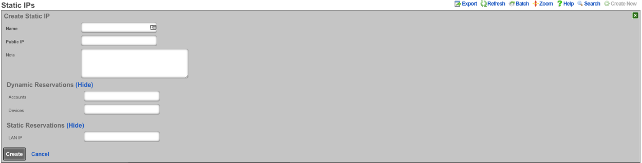
Static IPs
 Static IPs scaffold for configuring one-to-one NAT mappings
An entry in the Static IPs scaffold creates a one-to-one mapping between an IP address within a span associated with an uplink and a private IP address on the LAN. This feature is typically used to give public access to a resource that is configured on a private IP address such as a web server.
The name field is an arbitrary string descriptor used only for administrative identification. Choose a name that reflects the purpose of the record. This field has no bearing on the configuration or settings determined by this scaffold.
The Source IP field determines the destination of the translation of traffic originating from the Public IP.
The Public IP field specifies the IP address within a span of addresses associated with an uplink that will be translated to the Source IP.
The note field is a place for the administrator to enter a comment. This field is purely informational and has no bearing on the configuration settings.
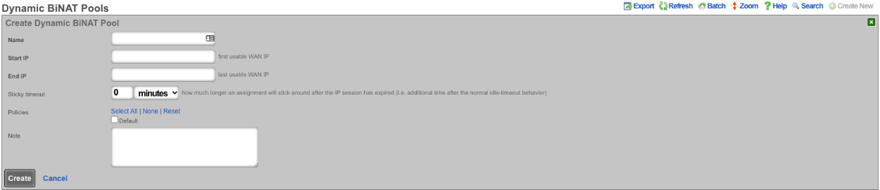
Dynamic BiNAT Pools
 Dynamic BiNAT Pools scaffold for configuring dynamic dedicated IP assignments
An entry in the Dynamic BiNAT Pools scaffold specifies a range of IP addresses that may be dynamically assigned to devices whose account has a Max BiNATs value of 1 or greater, and whose policy is enabled for this Dynamic BiNAT Pool. This feature is typically used to give public access to a resource that is configured on a private IP address such as a web server or a gaming device which requires open incoming firewall ports for proper operation.
The end-user may subscribe to a usage plan which allows Dynamic BiNAT, and may enable BiNAT functionality for specific device(s) by accessing the manage devices page of the portal. The operator may also change the active BiNAT device(s) by editing the account's device list. Care must be given to ensure that the range of addresses configured here is large enough to accommodate the number of devices that are configured for Dynamic BiNAT.
The name field is an arbitrary string descriptor used only for administrative identification. Choose a name that reflects the purpose of the record. This field has no bearing on the configuration or settings determined by this scaffold.
The Start IP field determines the first IP address of the range of uplink addresses that will be used as the Dynamic BiNAT IP for eligible devices. The IP should fall within a span of addresses associated with an uplink that is associated with the device's link control.
The End IP field specifies the last IP address in the range of uplink addresses that will be used as the Dynamic BiNAT IP for eligible devices. The IP should fall within a span of addresses associated with an uplink that is associated with the device's link control.
The Policies field specifies policies that may utilize this BiNAT Pool. When an associated Policy contains Accounts, a number of IPs specified in the Max BiNATs field of the Account will be assigned to that Account. The end user will be able to configure up to that many DMZ devices through the manage devices page in the captive portal. When an associated Policy contains devices that do not belong to an account, such as from an IP group or MAC group, a BiNAT will be assigned to each device currently connected that belongs to the associated Policy. If no policies are associated with this BiNAT pool, the pool is effectively disabled, and the addresses will be available for regular NAT.
The note field is a place for the administrator to enter a comment. This field is purely informational and has no bearing on the configuration settings.
Data Flow: Subscriber Onboarding and NAT Assignment
The following diagrams illustrate the end-to-end flow of how a subscriber device connects to the network, obtains an IP address, authenticates, gets assigned a NAT translation, and gains Internet access.
Device Connection Through Internet Access
sequenceDiagram
    participant UE as Subscriber Device
    participant AP as Access Point
    participant DHCP as DHCP Server<br/>(rXg)
    participant PF as Packet Filter<br/>(Policy Engine)
    participant CP as Captive Portal
    participant DB as rXg Database
    participant NAT as NAT Engine
    participant WAN as Internet<br/>(via Uplink)

    Note over UE,WAN: Phase 1  Network Attachment (L2/L3)

    UE->>AP: Associate with SSID
    AP-->>UE: Association confirmed<br/>(on default or DVLAN)
    UE->>DHCP: DHCP DISCOVER
    DHCP->>DHCP: Select pool<br/>(by VLAN, class rules)
    DHCP-->>UE: DHCP OFFER (IP, gateway, DNS)
    UE->>DHCP: DHCP REQUEST
    DHCP-->>UE: DHCP ACK
    DHCP->>DB: Record DHCP lease<br/>(IP, MAC, AP, lease time)

    Note over UE,WAN: Phase 2  Pre-Authentication (Captive Portal)

    UE->>PF: HTTP request to any site
    PF->>PF: Check policy for device<br/>(no LoginSession yet)
    PF-->>UE: HTTP 302 redirect<br/>(to captive portal)
    UE->>CP: Load portal landing page
    CP-->>UE: Login form<br/>(credentials / OAuth / SMS)

    alt Account Login
        UE->>CP: Submit credentials<br/>(username + password)
        CP->>DB: Authenticate<br/>(local DB / RADIUS / LDAP)
        DB-->>CP: Auth success + policy
    else MAC Automatic Login
        CP->>DB: Lookup MAC address<br/>(match against known devices)
        DB-->>CP: Auto-login granted + policy
    else Shared Credential
        UE->>CP: Submit shared password
        CP->>DB: Validate against<br/>SharedCredentialGroup
        DB-->>CP: Auth success + policy
    end

    CP->>DB: Create LoginSession<br/>(account, IP, MAC, online=true,<br/>expires_at, policy)

    Note over UE,WAN: Phase 3  NAT Assignment & Internet Access

    DB->>NAT: Assign NAT IP<br/>(from uplink pool)
    NAT->>NAT: Select public IP<br/>(CGNAT shared pool<br/>or dedicated BiNAT IP)
    NAT->>DB: Create NatAssignment<br/>(source_ip  nat_ip, uplink)
    NAT->>PF: Install NAT rule<br/>(source_ip  nat_ip)

    PF->>PF: Apply policy<br/>(bandwidth queues, content filter)

    UE->>PF: HTTP request
    PF->>NAT: Translate source IP<br/>(private  public)
    NAT->>WAN: Forward to Internet
    WAN-->>NAT: Response
    NAT->>PF: Translate destination IP<br/>(public  private)
    PF->>UE: Deliver response<br/>(QoS shaped)
NAT Pool Selection Logic
flowchart TD
    A[Device authenticates<br/>LoginSession created] --> B{Account has<br/>dedicated IP<br/>entitlement?}

    B -->|Yes: max_dedicated_ips > 0| C{BiNAT Pool<br/>has available IPs?}
    B -->|No| G[Assign shared CGNAT IP<br/>from uplink NAT pool]

    C -->|Yes| D{Static dedicated<br/>IPs enabled?}
    C -->|No| G

    D -->|Yes| E[Assign static dedicated IP<br/>reserved for account lifetime]
    D -->|No| F[Assign dynamic dedicated IP<br/>from BiNAT pool]

    E --> H[Create NatAssignment<br/>is_binat=true, static=true]
    F --> H2[Create NatAssignment<br/>is_binat=true, static=false]
    G --> I[Create NatAssignment<br/>is_binat=false]

    H --> J[Device gets 1:1 NAT<br/>Full inbound connectivity<br/>UPnP port forwards available]
    H2 --> J
    I --> K[Device shares public IP<br/>with other subscribers<br/>Port-based NAT translation]

    style A fill:#e1f5fe
    style J fill:#c8e6c9
    style K fill:#fff9c4
Session Lifecycle and Accounting
sequenceDiagram
    participant UE as Subscriber Device
    participant RXG as rXg Gateway
    participant RAD as RADIUS Server<br/>(if RADIUS auth)
    participant DB as rXg Database

    Note over UE,DB: Active Session  Periodic Updates

    loop Every accounting interval
        RXG->>RXG: Collect traffic stats<br/>(bytes/pkts up/down per IP)
        RXG->>DB: Update LoginSession counters<br/>(bytes_up, bytes_down)

        opt RADIUS accounting enabled
            RXG->>RAD: Accounting Interim-Update<br/>(Acct-Session-Time,<br/>Acct-Input/Output-Octets)
        end
    end

    Note over UE,DB: Session Termination

    alt User logs out
        UE->>RXG: Explicit logout request
    else Session expires
        RXG->>RXG: expires_at reached
    else Admin disconnects
        DB->>RXG: Admin destroys LoginSession
    else Idle timeout
        RXG->>RXG: No traffic for idle period
    end

    RXG->>DB: Destroy LoginSession
    DB->>DB: Final usage debit to account
    DB->>DB: Create LoginSessionLog<br/>(historical record)
    DB->>DB: Release NatAssignment<br/>(if dynamic)
    DB->>DB: Destroy VlanTagAssignment<br/>(if DVLAN configured)

    opt RADIUS accounting enabled
        RXG->>RAD: Accounting Stop<br/>(Acct-Terminate-Cause,<br/>final byte/packet counts)
    end

    opt CoA / Disconnect to AP
        RXG->>UE: Disconnect-Request<br/>(force de-authentication)
    end
NAT Pool Sizing Recommendations
Proper sizing of NAT pools is critical for network performance and subscriber experience. The recommended ratio of public IP addresses to concurrent devices varies based on deployment type.
Terminology: Throughout this section, sizing ratios are expressed as concurrent devices per public IP. A "device" is any network-connected endpoint (phone, laptop, tablet, smart TV, gaming console, etc.). In MDU contexts, a "subscriber" typically has multiple devices; in hospitality contexts, a "guest room" may contain several guests each with multiple devices. Always size based on expected peak concurrent device count, not subscriber or room count.
MDU (Multi-Dwelling Units) and Large Enterprise Deployments
For MDU deployments such as apartments, condominiums, and student housing, the recommended configuration is 1:1 (one public IP address per living unit). This configuration is preferred when subscribers require unrestricted inbound connectivity and provides:
- Full public IP functionality for each subscriber
- Support for gaming, hosting, and applications requiring open ports
- Simplified troubleshooting and traffic attribution
- Non-repudiation of online activities, assisting in subpoena and DMCA enforcement
- Easier provisioning of static IP options to subscribers
When using Dynamic BiNAT pools for MDU deployments, ensure the pool contains at least as many addresses as the expected number of concurrent subscribers.
Hotel and Hospitality Deployments
For transient environments such as hotels, convention centers, and similar hospitality venues, a ratio of 50:1 to 150:1 (50 to 150 concurrent devices per public IP address) is typically appropriate. The optimal ratio depends on usage patterns and guest expectations. This higher sharing ratio is appropriate because:
- Guest stays are temporary and connections are transient
- Guest traffic typically consists of web browsing and streaming
- Fewer guests require dedicated public IP functionality
- Cost optimization is often a priority
Sizing considerations:
- Use 50:1 to 100:1 for venues with heavy usage (tech conferences, gaming events, business travelers)
- Use 100:1 to 150:1 for typical leisure hospitality with light browsing and streaming
- Remember that device density varies significantly; a guest room may have 4-8+ devices (phones, tablets, laptops, smart TVs, wearables). Size based on observed peak concurrent device counts, not room or guest account numbers
Warning: Higher sharing ratios increase the risk of port exhaustion during peak usage. Each public IP provides tens of thousands of usable ports (the exact number depends on your configured port range and NAT timeout settings). Modern applications and devices often maintain dozens of simultaneous connections, so always validate your chosen ratio against observed port utilization. Monitor the NAT Pool Stats for signs of port exhaustion.
IPv6 consideration: Deploying dual-stack IPv6 can significantly reduce IPv4 NAT pressure, as IPv6-capable devices and services will bypass the NAT pool entirely. This allows for higher IPv4 sharing ratios without risking port exhaustion.
CGNAT (Carrier Grade NAT) can be used for the general guest population, with a smaller BiNAT pool available for guests who require dedicated IP functionality.
General Guidelines
When sizing NAT pools, consider the following:
- Peak concurrent users: Size pools based on maximum expected simultaneous connections, not total subscriber count
- Service tier mix: Account for the percentage of subscribers on plans that include BiNAT access
- Growth margin: Include headroom for subscriber growth to avoid pool exhaustion
- Static vs. dynamic: Static BiNAT assignments permanently consume addresses; dynamic assignments can be shared when subscribers disconnect
Use the NAT Pool Stats in the Instruments::NAT Assignments view to monitor pool utilization and identify when expansion is needed.
Example BiNAT Deployments
Below are 3 BiNAT deployment examples.
Example 1: Dynamic BiNATs
In this example the operator has configured the rXg to have a block of public IP address that are used for CGNAT and another pool that users can dynamically be assigned a public IP address from that can be used as NAT for the account. This IP can be assigned to a specific device (DMZ), and can also be used for UPnP.
First a block of public IP address must be assigned to an interface.
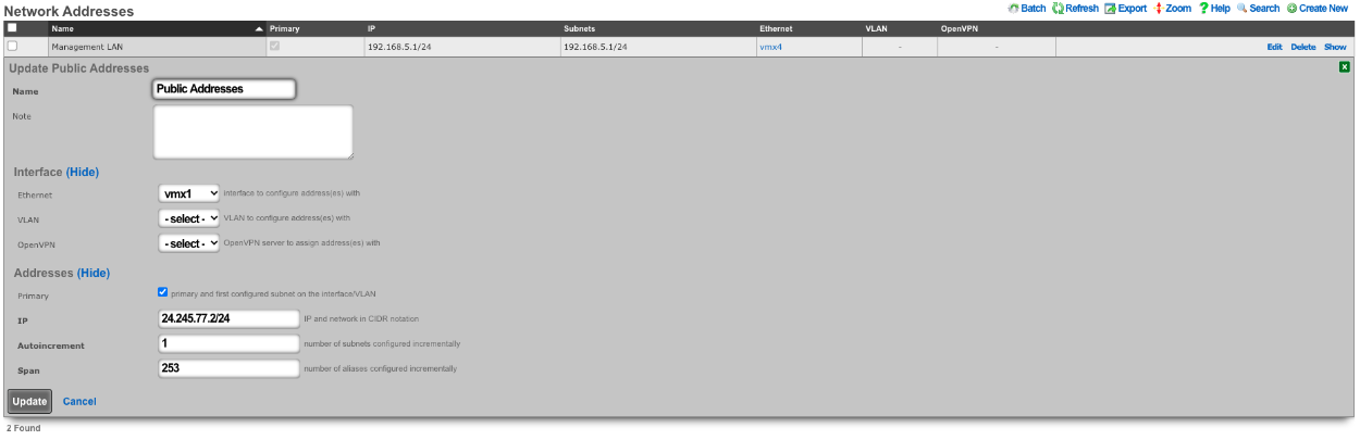 Public IP address block configured on the WAN interface
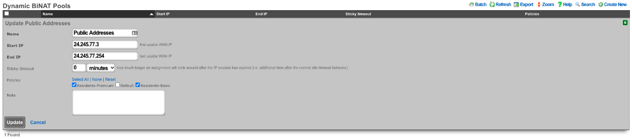
Next we need to configure a BiNAT pool by going to Network :: NAT, in this case half the public IP addresses will be used for BiNATs. The Operator can control which accounts/clients can be assigned a BiNAT by selecting the Policies that can use the pool. In this case only users in the Residents-Premium policy will be able to draw from the pool.
 BiNAT pool configured with half the public IPs for the Residents-Premium policy
Being in the Residents-Premium policy is not all that is required the account must also be set to allow the use of BiNAT IP address. This is controlled by the Usage Plan the user has purchased. This can be set by going to Billing :: Plans. Edit the appropriate Usage Plan and look at the Sessions section of the account. Here the Operator can set the number of Max dedicated IPs , in this example it is set to 1. UPnP has also been selected in this case.
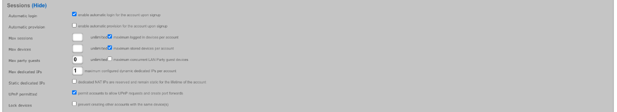 Usage Plan configuration with Max dedicated IPs and UPnP options
Now users who purchase the Residents-Premium plan will have a BiNAT assigned to their account that all the traffic from their devices will NAT through and their devices can create UPnP port forwards automatically.
Example 2: Static Dedicated BiNATs
In this example the rXg has been configured so that each account gets assigned a BiNAT that is static. First a block of public IP addresses must be configured.
Public IP address block configured on the WAN interface
Next the BiNAT pool must be configured to consume the entire block of public IP address, and the appropriate policies must be allowed access to the BiNAT pool. Network :: NAT.
 BiNAT pool consuming the full range of public IP addresses
The account must also be set to allow the use of BiNAT IP address. This is controlled by the Usage Plan the user has purchased. This can be set by going to Billing :: Plans. Edit the appropriate Usage Plan and look at the Sessions section of the account. Here the Operator can set the number of Max dedicated IPs , in this example it is set to 1. By checking the Static dedicated IPs box the NAT IP or IPs are reserved and remain static for the lifetime of the account. UPnP has also been selected in this case.
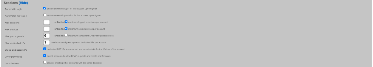 Usage Plan configuration with Static dedicated IPs enabled for permanent IP assignment
In this example each account is assigned a BiNAT address when created, and the IP assigned will remain for the lifetime of the account. This is the equivalent of having a static public IP address.
Example 3: BroadBand On Demand
In this example the rXg has been configured so that each account selects the number of Dedicated IPs (BiNAT addresses) that will be assigned to the account at time of purchase. A block of Public IP address must be configured via Network :: WAN.
Public IP address block configured on the WAN interface
Next the BiNAT pool must be configured to determine which IP address can be used for dedicated IPs, and the appropriate policies must be allowed access to the BiNAT pool. Network :: NAT.
BiNAT pool consuming the full range of public IP addresses
The Usage Plans for this example must be configured to allow the user to pick the number of Dedicated IPs by using the Plan Addons scaffold via Billing :: Plans. Here two Plan Addons have been created allowing the user to purchase additional Dedicated IPs and allows them to make them static by purchasing the static IP option.
 Plan Addons scaffold with dedicated IP purchase options
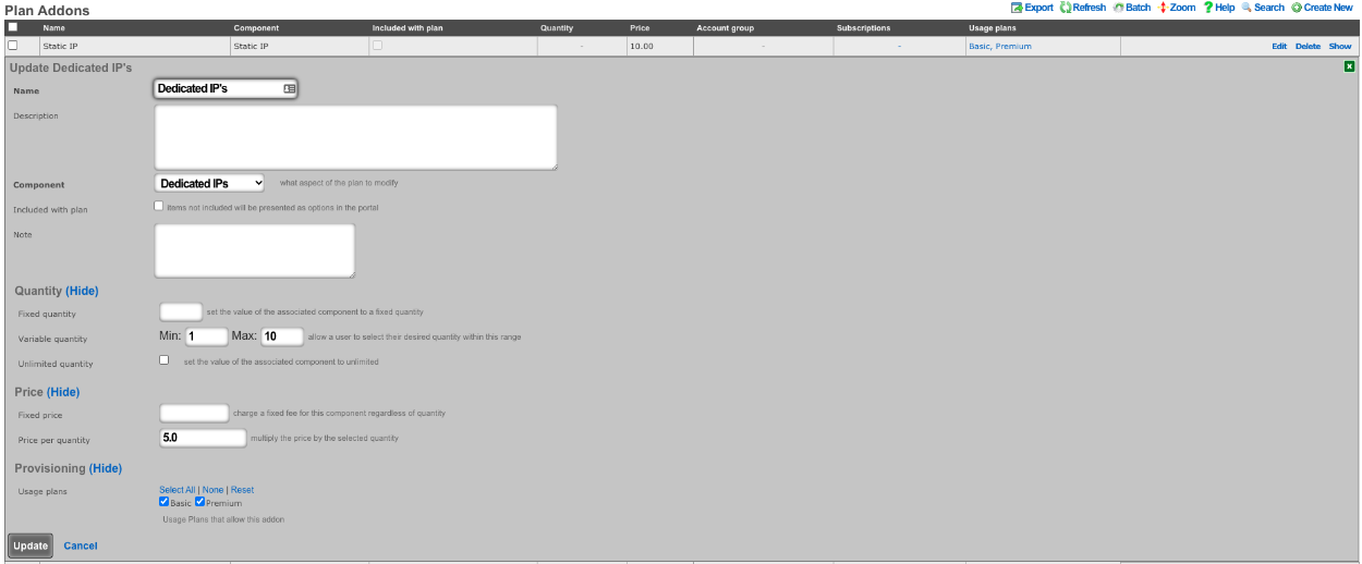 Plan Addon allowing users to purchase additional dedicated IPs
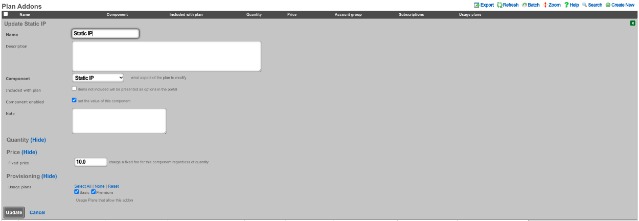 Plan Addon allowing users to make dedicated IPs static
The above configuration allows the user when purchasing a plan to select how many dedicated IPs they want and can purchase the ability to make them static as well.
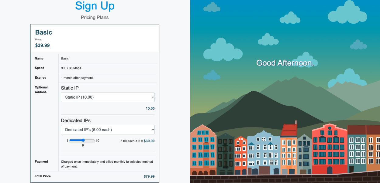 End-user portal showing dedicated IP and static IP addon options during plan purchase
Reverse NAT Example
Video Configuration Guide and Demonstration
In this example a NAT rule will be created for Reverse NAT. It will be assumed here that the ISP is handing out a private IP address and routing a static block of public IP addresses to the private IP address. Traffic that originates from the WAN IP address of the rXg will be NAT'ted to the first IP address of the public static block on the LAN. What this means is that if a client device were to go to whatismyipaddress it would report the first IP address of the static block on the LAN and not the WAN IP address. Inbound traffic from the Internet destined to the first IP address of the public static block on the LAN is now redirected to the WAN IP address of the rXg. This means that if the operator were to put in their browser the first Public IP address from the static LAN block, they would be getting to the WAN of the system.
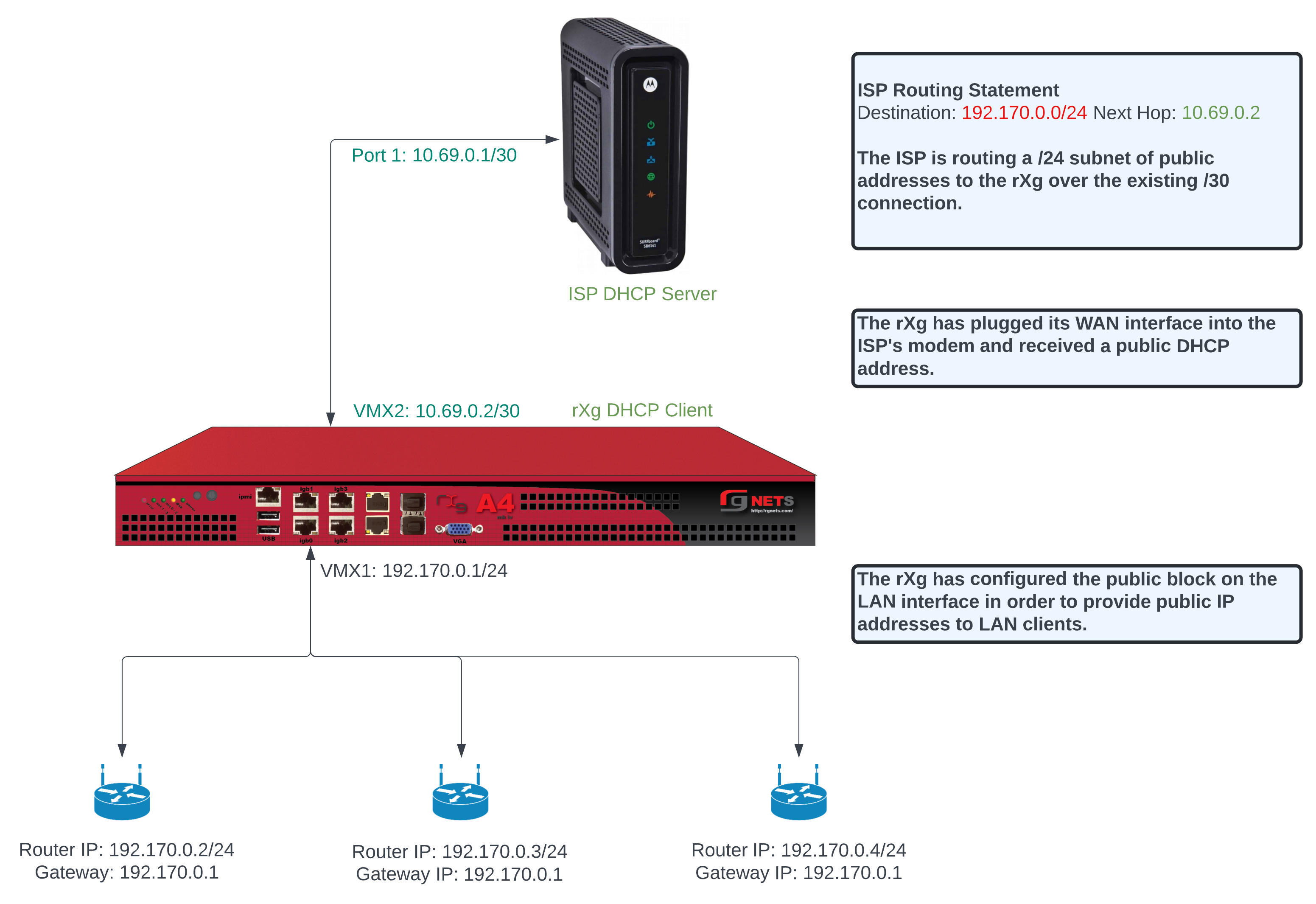 Reverse NAT concept diagram showing traffic translation between private WAN and public LAN addresses
To configure this there needs to be a WAN uplink that would usually be a static IP address however it could be DHCP that assigns a static IP, and there needs to be a block of static Public IP addresses routed to the uplink IP. Below is an example Uplink configuration that receives a WAN IP via DHCP.
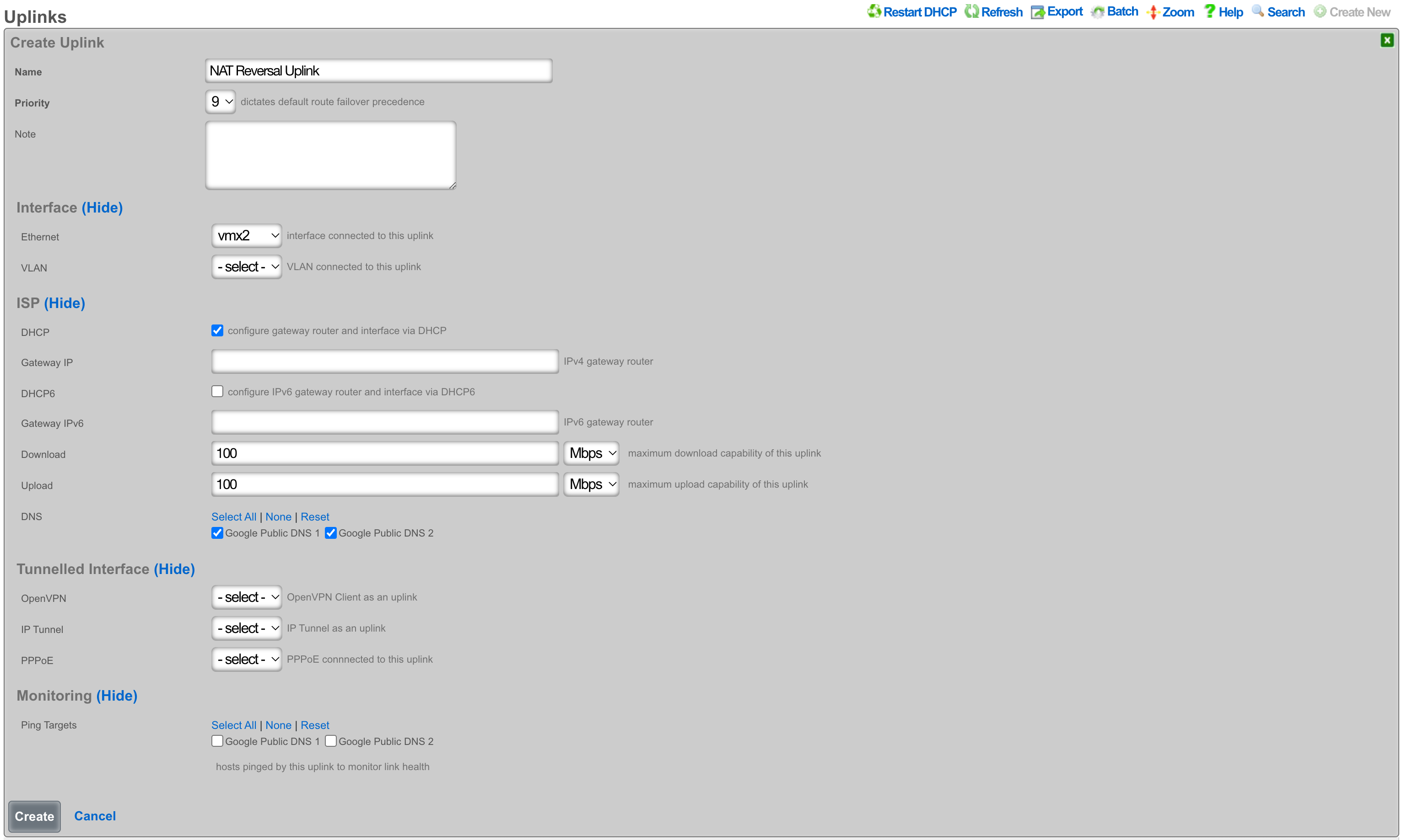 Uplink configuration receiving WAN IP address via DHCP
To configure this with an assigned static WAN IP address, create a new Uplink or edit an existing one. Select the interface. Make sure the DHCP box is unchecked, and enter the gateway IP address. Create or update the uplink.
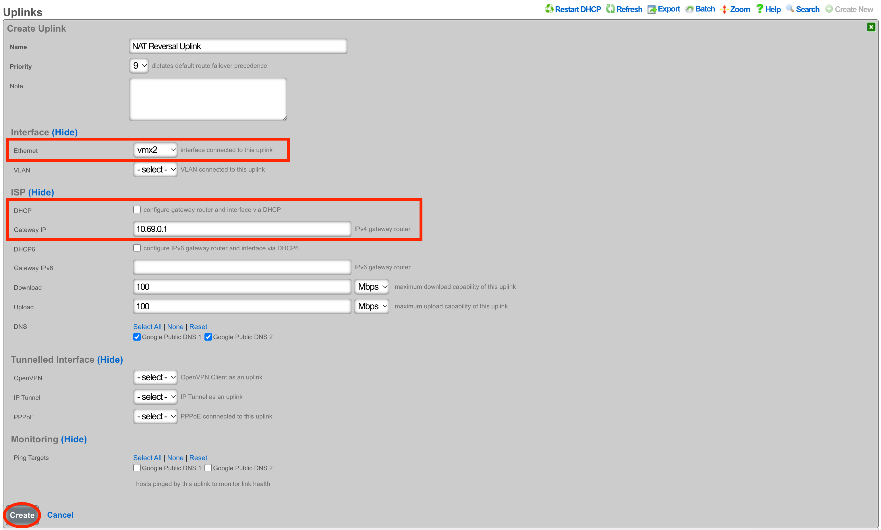 Uplink configuration with static WAN IP address and gateway
Next create a new Network Address and assign the IP address to the uplink. Give the Network Address a name, and select the interface, the interface should match the interface of the Uplink. Enter the address to be assigned to the uplink and click create.
 Network Address configuration assigning the WAN IP to the uplink interface
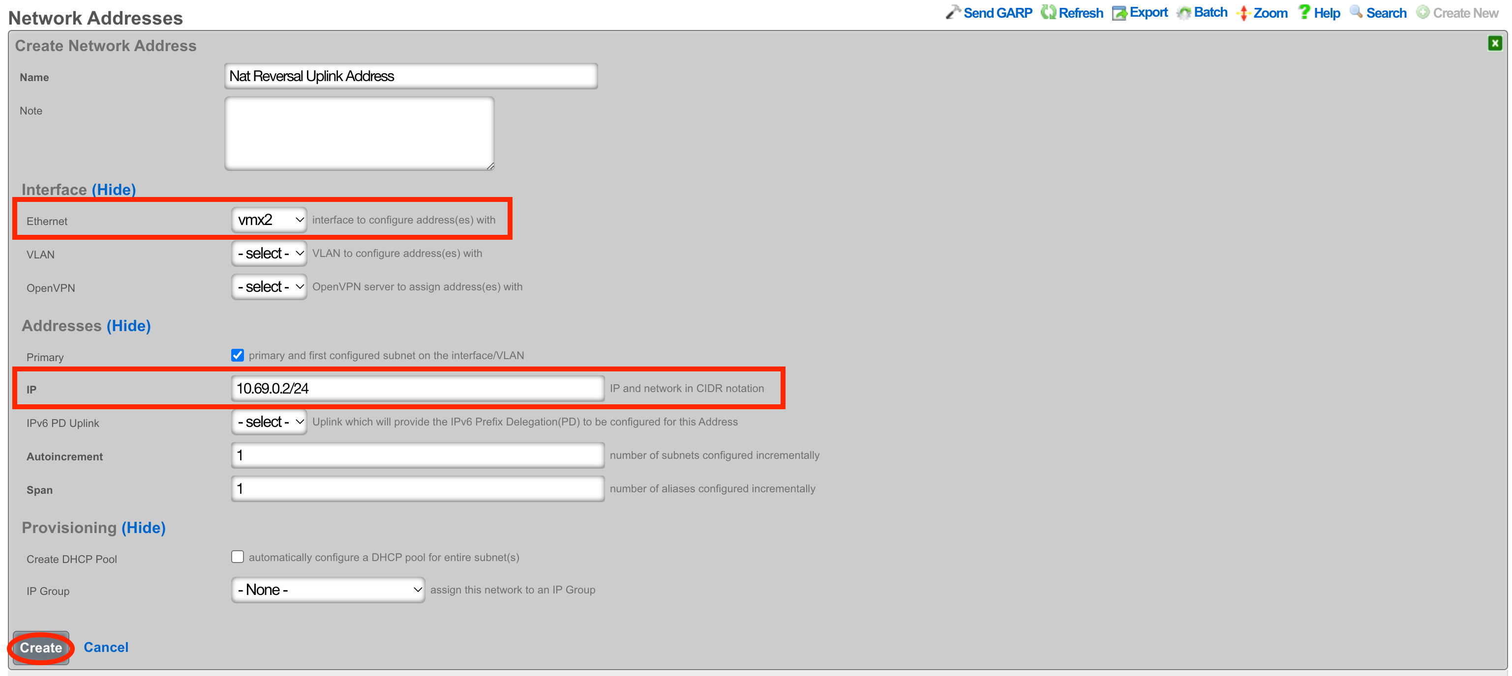
Next the Static Block of Public IP address will be created. Create a new Network Address. Give the record a name, select the interface that matches the uplink in this case it is vmx1. Enter the IP address in cidr notation. Only a single IP address is needed here however we can assign more to the system by adjusting the span if needed. Setting the span to 2 in this example would assign the .2 and .3 address to the system. Click Create.
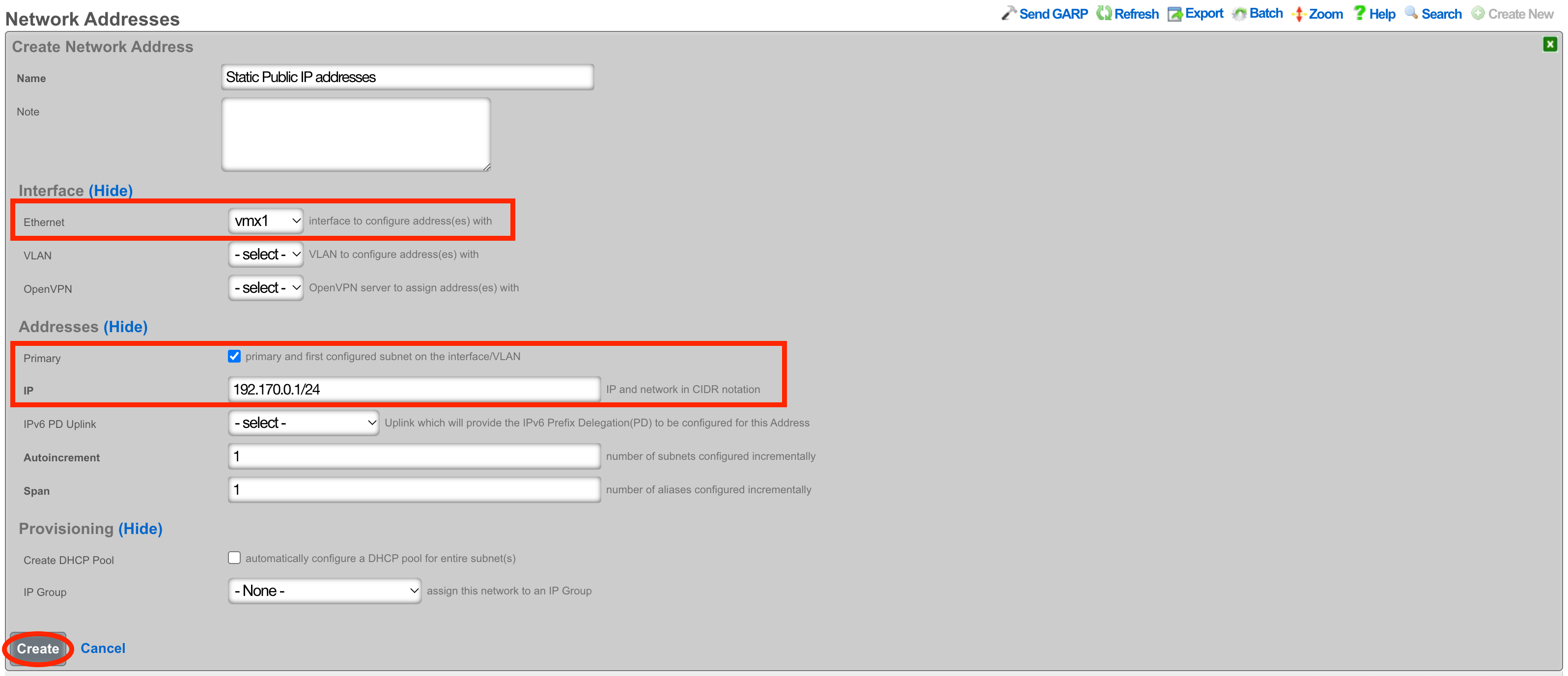 Network Address configuration for the static public IP block routed by the ISP
Next navigate to Network :: NAT and create a new NATs rule.
 NAT scaffold ready for creating a new Reverse NAT rule
Give the record a name, select the Uplink and check the Reverse NAT box. Next select the Network Address created in the previous step and click Create.
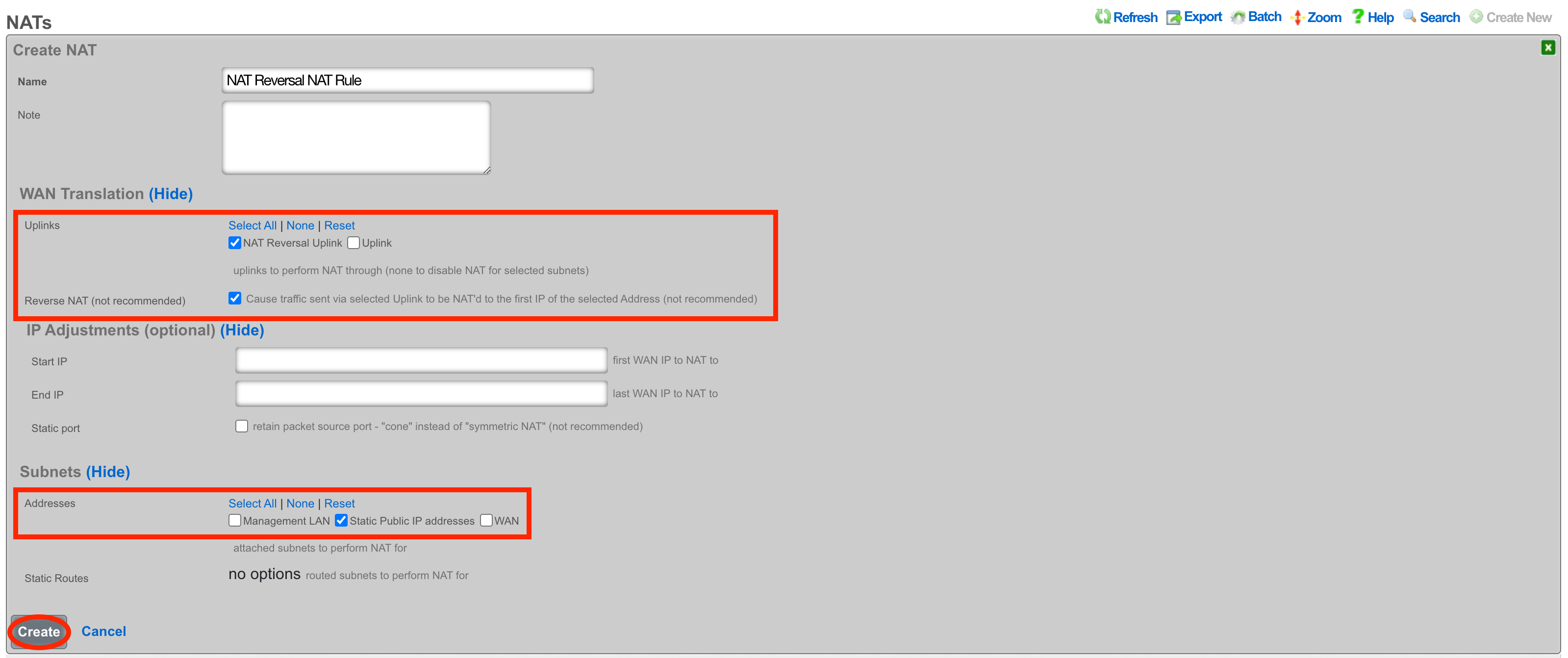 Reverse NAT rule configuration with uplink and public address block selected
With this configuration in place, a device on the LAN that goes to whatismyipaddress.com would report that its IP address was 203.0.113.1. A device going to https://203.0.113.1/admin would get the Admin GUI of the system, even though the uplinks IP is a private address.


