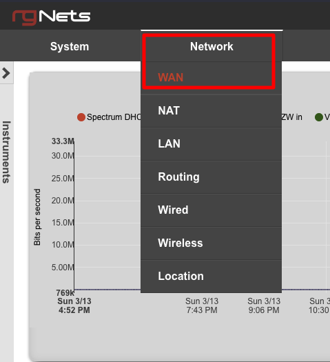
WAN
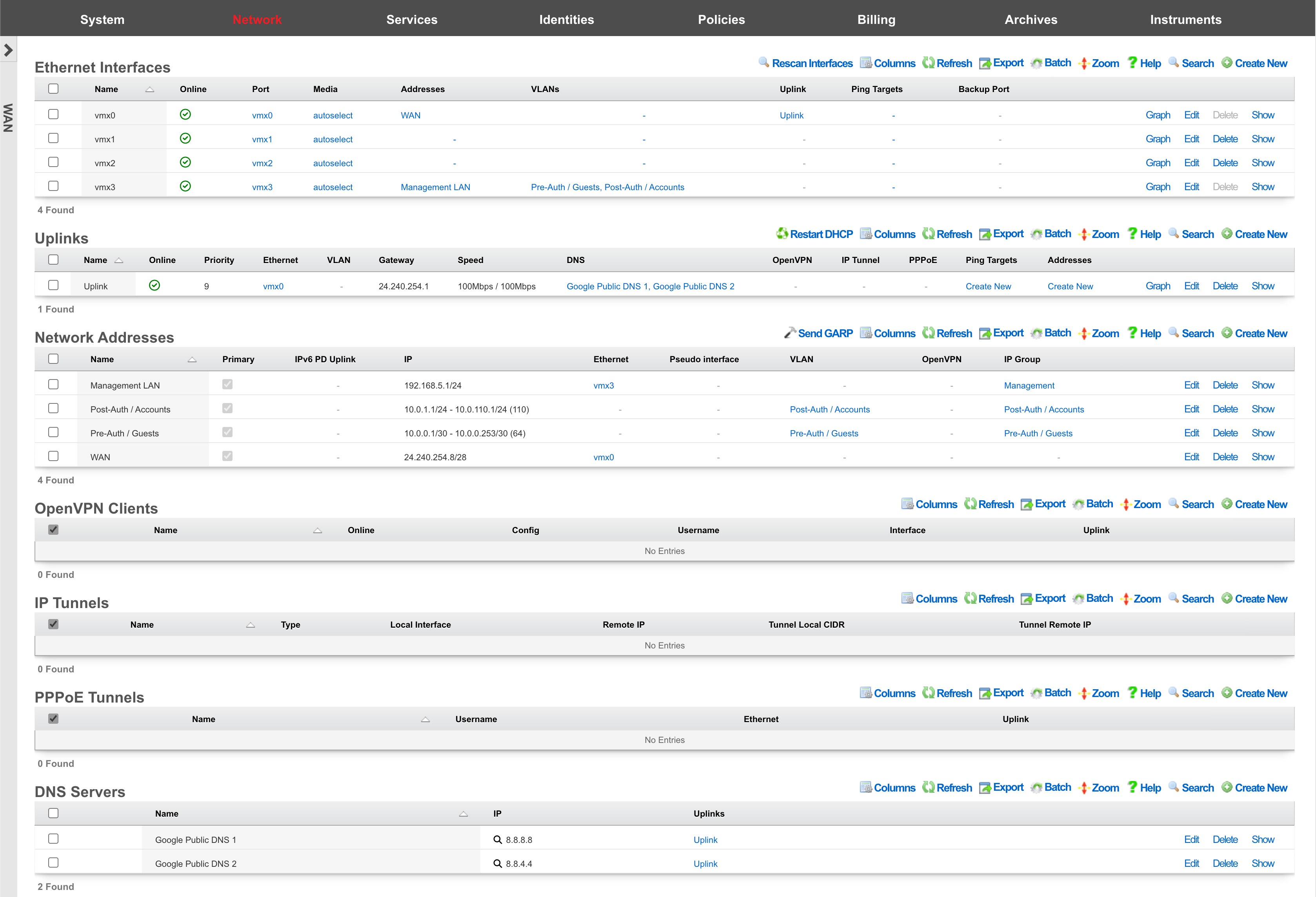
The WAN view presents the scaffolds associated with configuring the wide area network interfaces.
An rXg requires at least one properly configured entry in the uplinks scaffold in order to function. If more than one uplink is configured, the rXg can aggregate and failover WAN uplinks. In addition, the rXg can affine and diversity LAN traffic over the WAN uplinks.
An uplink must be configured with a valid IP address and gateway to function. To use DHCP to obtain an IP address and gateway dynamically, simply check the DHCP checkbox in the uplink record. As an alternative, a static IP address may be manually specified by creating a record in the addresses scaffold and associating the record with an uplink. The gateway for a statically assigned IP block must be manually configured in the uplink record. If the upstream ISP requires PPPoE authentication, configure the ISP supplied credentials into a record of the PPPoE scaffold and associate the record with the uplink.
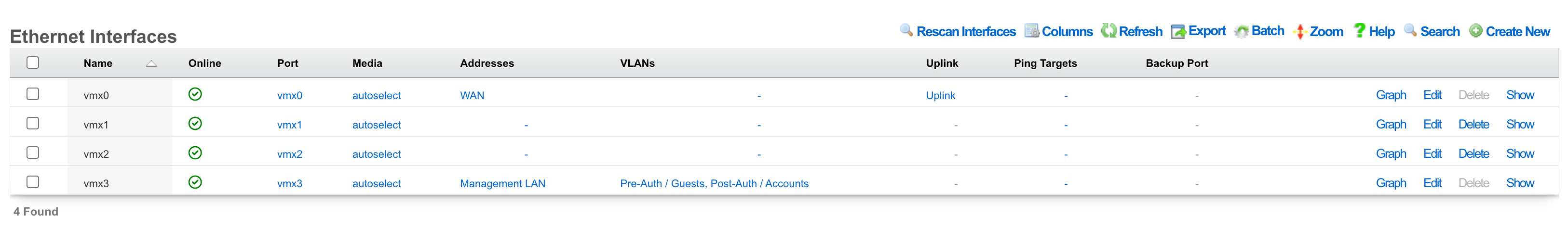
Ethernet Interfaces
An entry in the ethernet interfaces activates and configures a physical port on the rXg to take part in in networking connectivity.
In most cases, at least two ethernet interfaces must be configured (one for the WAN, one for the LAN). In multiple uplink scenarios, it is common to have one ethernet interface configured for each WAN uplink. It is also possible to use VLANs on a single ethernet interface to configure unlimited WAN and LAN interfaces.
The name field is an arbitrary string descriptor used only for administrative identification. Choose a name that reflects the purpose of the record. This field has no bearing on the configuration or settings determined by this scaffold.
The port field determines the physical ethernet port that this record will activate and configure.
The media field configures the speed and duplex of the Ethernet port. In most cases, the autoselect setting will automatically negotiate the fastest possible link. Autoselect should also be used if automatic crossover detection is required as most Ethernet hardware will disable automatic crossover if anything other than autoselect is specified as the media type.
If physical link cannot be established, first check the physical cable using an isolation test. If the cable is determined to not be the issue, try setting the ethernet interfaces on both sides of the cable to the same speed and duplex. Note that if a straight cable is connected between two nodes, that cable will need to be replaced with a crossover because automatic crossover detection will be disabled when a media type other than autoselect is specified. In addition, using a lower speed setting and avoiding full-duplex communication may be necessary when the cable is long or does not meet the standards needed for higher speed communication.
The MTU setting configures the maximum transmission unit (frame size) for this interface. By default, most ethernet interfaces support 1500 bytes. Large MTUs may be used in gigabit networks that support jumbo frames to obtain better throughput when transferring large files. Support for jumbo frames must be present throughout the infrastructure in order for larger MTUs to work properly.
The addresses , uplink , VLANs and PPPoE fields link an Ethernet interface to a configuration defined by the specified scaffold. These fields shown here are mainly presented for informational purposes. In most scenarios, an administrator will link the address, uplink, VLAN or PPPoE configuration to the Ethernet interface using the other scaffold.
The backup port field specifies an alternative ethernet interface to assign the addresses , uplink , VLANs and PPPoE configuration settings when this ethernet interface goes down. An ethernet interface is marked as down if it loses link or if all of the ping targets associated with it go offline. The VLANs and Network Addresses associated with an ethernet interface are moved to the backup port when the ethernet interface is marked as down. The backup port mechanism is designed to be used with generic L2 switching. Backup ports should not be used with any LAG/MLT/SMLT/LACP configuration on the connected switch.
The checksum offload , TCP segmentation offload and large receive offload settings offload the specified processing to the NIC hardware when possible. In some cases this may cause instability and in other cases there are performance benefits.

Uplinks
An entry in the uplinks scaffold declares a specified logical interface as a WAN uplink. At least one uplink must be configured for proper rXg operation. More than one uplink may be configured in multiple uplink control scenarios when the operator has obtained multiple WAN drains. When multiple uplinks are configured, the rXg can aggregate and failover between uplinks as well as diversify and affine LAN traffic amongst them.
The name field is an arbitrary string descriptor used only for administrative identification. Choose a name that reflects the purpose of the record. This field has no bearing on the configuration or settings determined by this scaffold.
The priority field determines the order of precedence during failover in a multiple uplink control scenario. When only one uplink is configured, this field has no effect as there is no uplink to failover to. When multiple uplinks are configured and connection aggregation is enabled, a failure of a link will cause another member of the pool to forward all traffic. If aggregation is not enabled, or all uplinks within a pool have failed, then the uplink with the highest priority amongst all of the remaining uplinks will be used to forward the traffic.
The interface , PPPoE and VLAN drop downs specifies the mechanism by which this uplink will forward traffic upstream. Only one option may be selected for each uplink.
The DHCP checkbox enables the DHCP client for this uplink. The network address, subnet mask and default gateway of this uplink are requested from the DHCP server. If a statically configured IP address is desired, leave this checkbox cleared, create a record in the addresses scaffold and associate it with this uplink.
The gateway IP specifies a statically assigned default gateway for this uplink. The default gateway must be within the IP block defined by the network address associated with this uplink. This field should remain blank if the DHCP checkbox is set.
The upload speed and download speed fields describe the throughput of the uplink. These values are used for traffic shaping calculations and should accurately reflect the actual capacity of the connection. The upload speed must be at least 2% of the download speed (for ACK queue accounting).
IPv6 Configuration
The DHCP6 checkbox enables the DHCPv6 client for this uplink. When enabled, the rXg will request an IPv6 address and optionally a delegated prefix from the upstream provider.
The gateway IPv6 field specifies a statically assigned IPv6 default gateway for this uplink. This field should remain blank if the DHCP6 checkbox is set.
The prefix delegation size field (visible when DHCP6 is enabled) specifies the size of the IPv6 prefix to request from the upstream provider, typically /48, /56, or /64 depending on ISP policy.
The send IPv6 prefix hint checkbox requests a specific prefix from the ISP during DHCPv6 negotiation. This is useful when the ISP supports prefix hints and the operator wishes to maintain a consistent IPv6 prefix.
Tunneled Uplink Options
For VPN-based uplinks, the following options are available (mutually exclusive with physical interfaces):
The OpenVPN client field associates this uplink with an OpenVPN tunnel configured under Network :: VPN :: OpenVPN Clients. Traffic using this uplink will exit through the VPN tunnel.
The tunnel interface field associates this uplink with an IP tunnel (GIF, GRE, etc.) configured under Network :: WAN :: IP Tunnels.
The PPPoE field associates this uplink with a PPPoE connection. When using PPPoE, do not associate the uplink directly with an Ethernet interface.
Health Monitoring
The ping targets field associates ping targets with this uplink for health monitoring. Each uplink should have at least two ping targets configured to enable proper failover detection. When all ping targets for an uplink fail, the uplink is marked offline and traffic is routed through remaining healthy uplinks.
The skip dataplane HA checkbox excludes this uplink from high-availability failover synchronization. This is useful for backup uplinks that should not trigger HA events.
Auto-Created Ping Targets
When creating an uplink with a static gateway, the rXg automatically creates ping targets for the gateway IP addresses:
[Uplink Name] Gateway- monitors the IPv4 gateway[Uplink Name] IPv6 Gateway- monitors the IPv6 gateway (if configured)
These auto-created targets help ensure basic gateway reachability is monitored.
Validation Rules
- At least one connection method is required (DHCP, static gateway, or tunnel)
- DHCP and static gateway are mutually exclusive (for each IP version)
- Upload bandwidth cannot exceed download bandwidth
- Upload must be at least 2% of download
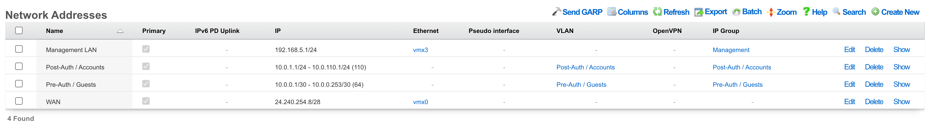
Network Addresses
An entry in the network addresses scaffold defines an IP block that will be associated with an interface, uplink or VLAN.
The name field is an arbitrary string descriptor used only for administrative identification. Choose a name that reflects the purpose of the record. This field has no bearing on the configuration or settings determined by this scaffold.
The IP field specifies the IP address using CIDR notation that will be configured on the interface specified. If the address record will be used for configuring multiple addresses on the interface via the span field, the IP field configures the first (lowest) IP address of the range.
The span field specifies the range of IP addresses configured by this address record. The default value of 1 is assumed if this field is omitted. For LAN links, a span of 1 is typical. For WAN links, a span of greater than 1 automatically enables translation pooling in NAT scenarios. In addition, bidirectional network address translation (BiNAT) requires the WAN link to span one additional address for each BiNAT.

PPPoE Tunnels
An entry in the PPPoE tunnels scaffold enables the point-to-point protocol over Ethernetclient to connect with the specified credentials through an Ethernet interface for the purpose of configuring a valid uplink.
The username and password fields specify the credentials for the PPPoE client. The credentials are assigned by the upstream ISP.
The service name is an optional service selector. If the upstream ISP did not provide a specific value, leave this field blank.
The interface field associates this PPPoE tunnel with an Ethernet interface. It is highly recommended that an Ethernet interface associated with a PPPoE tunnel be used exclusively for this purpose. Avoid associating addresses, VLANs, and other entities with an Ethernet interface that is designated for a PPPoE tunnel.
The uplink field associates this PPPoE tunnel with an uplink. To use PPPoE, an uplink must be associated with a record in the PPPoE tunnels scaffold, which in turn, is associated with a Ethernet interface. Do not associate an uplink that has a PPPoE tunnel enabled with the Ethernet interface directly.

DNS Servers
An entry in the DNS servers scaffold specifies an upstream DNS server to use for DNS resolution.
It is highly recommended that at least one upstream DNS servers be configured for network resilience, else the built-in DNS server is used for resolution. Without DNS resolution, no networking services will operate.
Many ISPs will provide DNS server entries. These DNS servers should be configured into this scaffold. In a multiple uplink control scenario where multiple uplinks from a diverse set of ISPs are configured in parallel, the DNS servers for all of the upstream ISPs should be configured with the appropriate uplink setting selected. In this case, theGoogle Public DNS or OpenDNS servers may be used as backup DNS servers for all uplinks.
The IP field specifies the IP address of the DNS server that is to be used for DNS queries. In most cases, the upstream ISP will provide the IP addresses for the public DNS servers for a specific uplink. If no servers are provided, using the Google Public DNS orOpenDNS is a good alternative.
The uplinks field associates uplinks with the DNS server specified in this record. In many cases, the upstream ISP will have DNS servers that are restricted to their customers so it is important to make sure that the right IP is associated with the proper uplink.
Recommended Ping Targets
For reliable uplink health monitoring and failover, configure ping targets that are external to the ISP network, highly available, and respond to ICMP requests. Common choices include:
| Target | Provider | Notes |
|---|---|---|
| 8.8.8.8 | Google Public DNS | IPv4 |
| 8.8.4.4 | Google Public DNS | IPv4 |
| 1.1.1.1 | Cloudflare DNS | IPv4 |
| 1.0.0.1 | Cloudflare DNS | IPv4 |
| 9.9.9.9 | Quad9 DNS | IPv4 |
| 208.67.222.222 | OpenDNS | IPv4 |
| 2001:4860:4860::8888 | Google Public DNS | IPv6 |
| 2001:4860:4860::8844 | Google Public DNS | IPv6 |
| 2606:4700:4700::1111 | Cloudflare DNS | IPv6 |
| 2606:4700:4700::1001 | Cloudflare DNS | IPv6 |
Using external targets (rather than ISP infrastructure) enables detection of upstream connectivity issues, peering problems, and ISP outages that would not be detected by pinging the gateway alone.
Configure IPV6 to IPV4 Tunnel
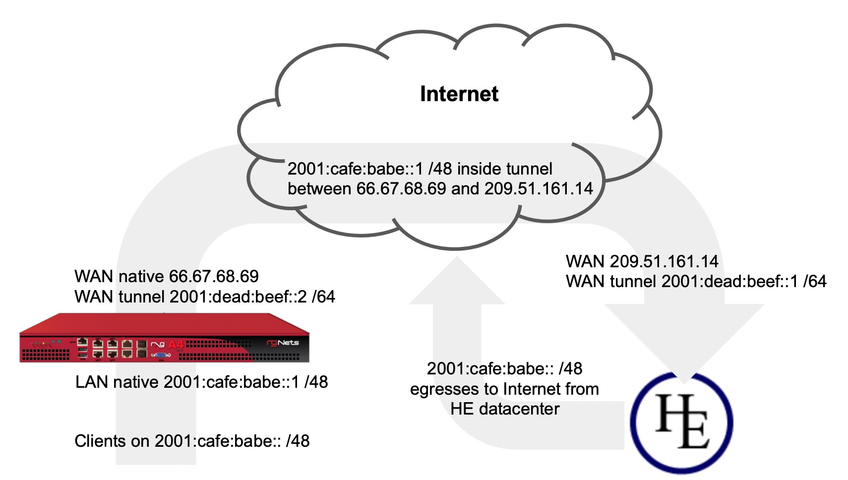
In this example we will configure the rXg with an IP tunnel that will allow us to access IPv6 addresses over an existing IPv4 connection. The IPv6 tunnel end point is provided by https://ipv6.he.net after passing a basic certification process. We will need to create an IP Tunnel, an Uplink, a Network Address, and lastly a DHCP pool. To begin navigate to Network::WAN.
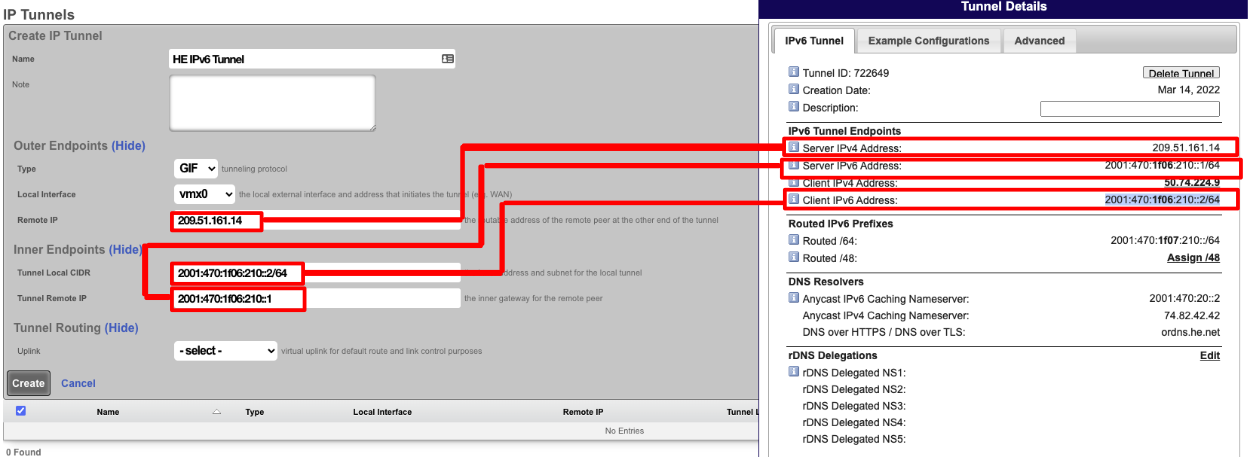
First we will create an IP Tunnel.

Give the IP Tunnel a name. The Type field should be set to GIF. Set the Local Interface field to the WAN interface. The Remote IP field is the Server IPv4 Address obtained from he.net. The Tunnel Local CIDR field is the Client IPv6 Address obtained from he.net. The Tunnel Remote IP is the Server IPv6 Address obtained from he.net. Click Create.
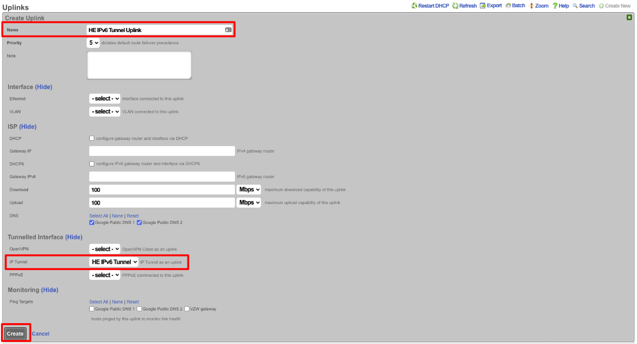
Next create a new Uplink, give the uplink a name, priority should be lower than your primary uplinks. Change the IP Tunnel field to the IP Tunnel created in the previous step. Click Create.
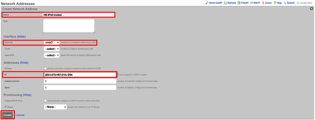
Next create a new Network address to create the LAN DHCP addresses that the system will hand out to IPv6 enabled clients. Give the Network addresses a name, select the ethernet interface the addresses will be configured on, and fill out the IP field with the information obtained from HE, in the Routed IPv6 Prefixes section. Note that the address given ends with :: which is invalid so append the IP you want to assign to the system usually 1. Checking the Create DHCP Pool box is optional, for this example setup it will not be checked and we will create the DHCP pool. Click Create.
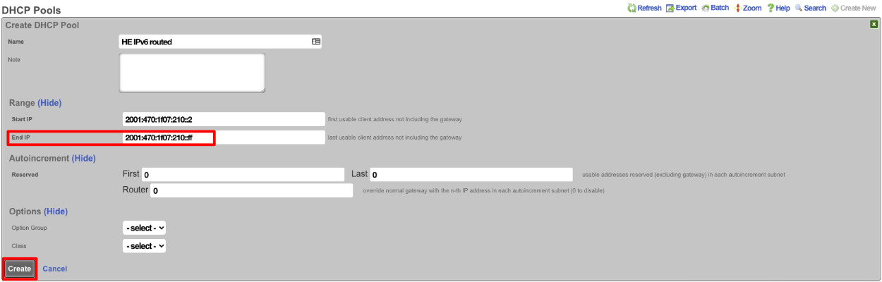
Next navigate to Services::DHCP and create a new DHCP pool. As long as the last address created was the address from the previous step it will auto fill the fields. It may be a good idea to reduce the scope of the pool by changing the end IP from 2001:470:1f07:210:ffff:ffff:ffff:ffff to 2001:470:1f07:210::ff. Click Create
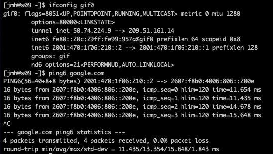
Now if we SSH into the machine and run ifconfig gif0 we should see our intferface configured with the IPv4 Tunnel addresses as well as the IPv6 Address, and we should be able to ping an IPv6 addressing using ping6 like ping6 google.com.
Multiple Uplink Configuration Scenarios
When multiple uplinks are configured, the rXg provides sophisticated traffic management across all available WAN connections. Understanding how the system selects uplinks is essential for proper configuration.
How Default Routing Works
When multiple uplinks are configured, the rXg selects the highest-priority online uplink as the default route. All traffic traverses this uplink unless:
- The uplink fails health checks (becomes offline)
- An Uplink Control policy directs traffic to a different uplink
- An Uplink Control rule specifies load balancing across multiple uplinks
The priority field (1-9, higher = more preferred) determines failover order. When the primary uplink fails, traffic automatically shifts to the next highest-priority online uplink. When the primary recovers, traffic returns to it.
Operating Modes
The rXg supports four primary multi-uplink operating modes:
| Mode | Description | Configuration Approach |
|---|---|---|
| Bandwidth Aggregation | Combine multiple uplinks for increased total bandwidth | Single Uplink Control with multiple uplinks, traffic distributed by weight |
| Uplink Failover | Primary uplink with automatic failover to backup | Two Uplink Control records (primary + backup with Backup flag) |
| Carrier Diversity | Multiple ISPs with health-based routing | Ping targets that traverse each ISP's network to external hosts |
| Application Affinity | Route specific traffic types through designated uplinks | Multiple Uplink Control records with Applications or WAN Targets filters |
These modes can be combined. For example, aggregating two fiber uplinks while maintaining a cellular backup with application affinity for VoIP.
The following scenarios demonstrate common configurations, providing more complex and mission oriented options.
Configure Two Uplinks with Failover
This walkthrough demonstrates configuring a primary and backup uplink with automatic failover.
Step 1: Configure the Primary Uplink
- Navigate to Network :: WAN :: Uplinks
- Click Create New
- Fill in the form:
| Field | Value | |-------|-------| | Name | Primary - Fiber | | Priority | 9 | | Interface | em0 (or your primary interface) | | DHCP | Checked | | Download Bandwidth | 1000 Mbps | | Upload Bandwidth | 1000 Mbps |
- Click Create
Step 2: Configure the Backup Uplink
- Click Create New again
- Fill in the form:
| Field | Value | |-------|-------| | Name | Backup - Cable | | Priority | 5 | | Interface | em1 (or your backup interface) | | DHCP | Checked | | Download Bandwidth | 100 Mbps | | Upload Bandwidth | 10 Mbps |
- Click Create
Step 3: Configure Ping Targets for Primary Uplink
- Navigate to Network :: WAN :: Ping Targets
- Click Create New
- Fill in the form:
| Field | Value | |-------|-------| | Name | Google DNS Primary | | Target | 8.8.8.8 | | Timeout | 3.0 | | Attempts | 6 | | RTT Tolerance | 100 | | Packet Loss Tolerance | 20 | | Uplinks | Primary - Fiber |
- Click Create
- Repeat to create a second ping target using 1.1.1.1 (Cloudflare DNS)
Step 4: Configure Ping Targets for Backup Uplink
Create two more ping targets for the backup uplink using different target IPs (e.g., 8.8.4.4 and 9.9.9.9) and associate them with the Backup - Cable uplink.
Step 5: Create Uplink Control Records
Navigate to Policies :: Uplink Control to create the primary and backup Uplink Control records. See the Uplink Control section for detailed configuration.
Verification
- Check Network :: WAN :: Uplinks - both should show Online status
- To test failover, disconnect the primary uplink and verify traffic continues via backup
- Reconnect primary and verify traffic returns to it
Configure Load Balancing Across Two Uplinks
This walkthrough demonstrates configuring two uplinks for load-balanced traffic distribution.
Step 1: Configure Both Uplinks
Follow the uplink creation steps from the failover scenario, but set both uplinks to the same priority (e.g., priority 9).
Step 2: Configure Ping Targets
Ensure each uplink has at least two ping targets configured.
Step 3: Adjust Weight Distribution
To customize traffic distribution based on bandwidth:
- Navigate to Policies :: Uplink Control
- Locate the Uplinks section (a separate scaffold on the same page)
- Edit each uplink to adjust its Weight value
Example for 75%/25% distribution: - Primary - Fiber: weight = 3 - Backup - Cable: weight = 1
Traffic calculation: 3/(3+1) = 75% through fiber, 1/(3+1) = 25% through cable.
Note: Weight is a global property of the uplink. Changing it affects all Uplink Controls that include it.
Step 4: Create Load-Balanced Uplink Control
Navigate to Policies :: Uplink Control and create a single Uplink Control record containing both uplinks. Traffic will be distributed according to weight ratios.
Configure VoIP Traffic Through Dedicated Uplink
This walkthrough demonstrates application-based routing for VoIP traffic.
Prerequisites
- Two configured uplinks with ping targets
- VoIP-related Applications defined in Services :: Application Control :: Applications
Configuration
- Navigate to Policies :: Uplink Control
- Create an Uplink Control record for VoIP:
| Field | Value | |-------|-------| | Name | VoIP Dedicated | | Uplinks | (select low-latency uplink) | | Applications | SIP, RTP (select VoIP apps) | | Policies | (select applicable policies) |
- Create a second Uplink Control record for default traffic:
| Field | Value | |-------|-------| | Name | Default Traffic | | Uplinks | (select remaining uplinks) | | Applications | (leave empty for all other traffic) | | Policies | (same policies) |
VoIP traffic will route through the dedicated low-latency uplink while all other traffic uses the default Uplink Control.
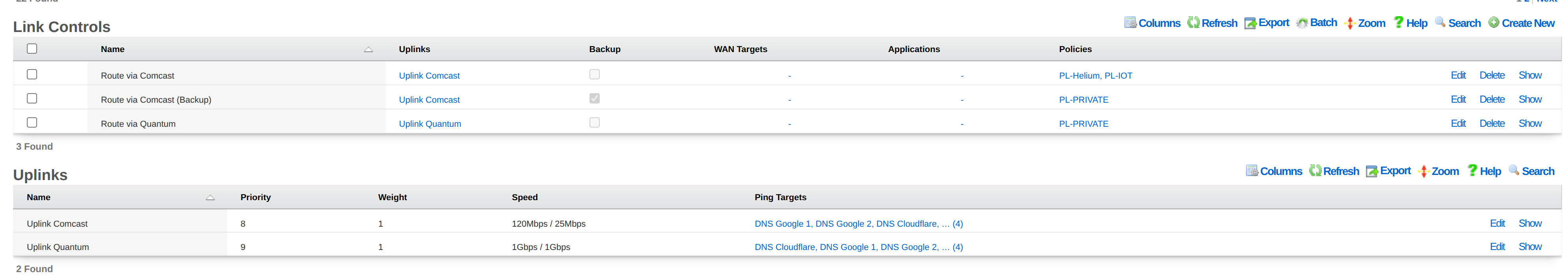
Configure Dual-Stack with Asymmetric IPv6 Support
This walkthrough demonstrates bandwidth aggregation for IPv4 across two uplinks where only one supports IPv6. This is common when one ISP provides IPv4-only service while another supports both IPv4 and IPv6.
Overview
| Uplink | IPv4 | IPv6 | Role |
|---|---|---|---|
| Quantum | Yes | No | IPv4 aggregation only |
| Comcast | Yes | Yes | IPv4 aggregation + exclusive IPv6 |
Goals: - IPv4 traffic load-balanced across both uplinks with failover protection - IPv6 traffic routed exclusively through the dual-stack uplink - Automatic failover if either uplink fails
Step 1: Configure the IPv4-Only Uplink
- Navigate to Network :: WAN :: Uplinks
- Click Create New
- Fill in the form:
| Field | Value | |-------|-------| | Name | Quantum - IPv4 Only | | Priority | 9 | | Interface | em0 | | DHCP | Checked | | DHCP6 | Unchecked | | Gateway IPv6 | (leave empty) | | Download Bandwidth | 500 Mbps | | Upload Bandwidth | 50 Mbps |
- Click Create
Do not configure any IPv6 settings on this uplink.
Step 2: Configure the Dual-Stack Uplink
- Click Create New
- Fill in the form:
| Field | Value | |-------|-------| | Name | Comcast - Dual Stack | | Priority | 9 | | Interface | em1 | | DHCP | Checked | | DHCP6 | Checked | | Prefix Delegation Size | 64 (or as provided by ISP) | | Download Bandwidth | 1000 Mbps | | Upload Bandwidth | 100 Mbps |
- Click Create
Enabling DHCP6 configures this uplink to receive an IPv6 address and prefix delegation. Since this is the only uplink with IPv6, all IPv6 traffic will automatically route through it.
Step 3: Configure Ping Targets
Create at least two ping targets for each uplink:
For Quantum (IPv4 only): - Target: 8.8.8.8 (Google DNS) - Target: 1.1.1.1 (Cloudflare DNS)
For Comcast (Dual Stack): - Target: 208.67.222.222 (OpenDNS) - IPv4 - Target: 9.9.9.9 (Quad9) - IPv4 - Target: 2001:4860:4860::8888 (Google IPv6) - optional - Target: 2606:4700:4700::1111 (Cloudflare IPv6) - optional
Step 4: Configure Weight Distribution
Adjust uplink weights based on available bandwidth:
- Navigate to Policies :: Uplink Control
- Locate the Uplinks section (a separate scaffold on the same page)
- Edit Quantum - IPv4 Only: set weight = 1 (for 500 Mbps)
- Edit Comcast - Dual Stack: set weight = 2 (for 1000 Mbps)
Traffic Distribution: - Quantum: 1/(1+2) = 33% of IPv4 traffic - Comcast: 2/(1+2) = 67% of IPv4 traffic - All IPv6 traffic: 100% through Comcast (only available path)
Step 5: Create IPv4 Load-Balanced Uplink Control
- Navigate to Policies :: Uplink Control
- Create an Uplink Control record containing both uplinks
IPv4 traffic is distributed across both uplinks according to weights. If one uplink fails, all IPv4 traffic automatically routes through the remaining uplink.
How IPv6 Routing Works
IPv6 routing requires no additional configuration:
- Automatic Path Selection: Since only Comcast has IPv6 configured, the rXg automatically routes all IPv6 traffic through that uplink
- No Uplink Control Needed for IPv6: IPv6 follows the only available default route
- Failover Behavior: If Comcast fails, IPv6 connectivity is lost (expected, as Quantum cannot carry IPv6)
Failover Behavior Summary
| Failure Scenario | IPv4 Behavior | IPv6 Behavior |
|---|---|---|
| Quantum offline | All traffic via Comcast | Unchanged (Comcast only) |
| Comcast offline | All traffic via Quantum | Unavailable |
| Both online | Load balanced by weight | Comcast only |
Configure VPN-Based Uplink
This walkthrough demonstrates configuring an OpenVPN tunnel as an uplink, allowing traffic to exit through a VPN provider or remote site.
Use Cases
- Privacy: Route traffic through a VPN provider
- Site-to-site: Connect branch offices through a central VPN
- Geo-restriction bypass: Access region-locked content
- Policy-based VPN: Route specific users or applications through VPN
Prerequisites
- OpenVPN server credentials (certificates, keys, or username/password)
- OpenVPN configuration file from the VPN provider
Step 1: Configure OpenVPN Client
- Navigate to Network :: VPN :: OpenVPN Clients
- Click Create New
- Fill in the form:
| Field | Value | |-------|-------| | Name | VPN Provider | | Remote | vpn.provider.com (or IP address) | | Port | 1194 (or provider-specified port) | | Protocol | UDP (or as specified by provider) | | Device Type | tun | | Certificate Authority | (upload or paste CA certificate) | | Client Certificate | (upload or paste client certificate) | | Client Key | (upload or paste client key) |
- Click Create
- Verify the connection establishes (check status shows connected)
Step 2: Create VPN Uplink
- Navigate to Network :: WAN :: Uplinks
- Click Create New
- Fill in the form:
| Field | Value | |-------|-------| | Name | VPN Uplink | | Priority | 5 (lower than primary uplinks) | | Interface | (leave empty) | | VLAN | (leave empty) | | OpenVPN Client | VPN Provider | | Download Bandwidth | (VPN provider's advertised speed) | | Upload Bandwidth | (VPN provider's advertised speed) |
- Click Create
Note: Leave the physical interface fields empty when using a VPN client. The uplink uses the tunnel interface created by OpenVPN.
Step 3: Configure Ping Targets
Create at least two ping targets for the VPN uplink:
| Field | Value |
|---|---|
| Name | Google DNS via VPN |
| Target | 8.8.8.8 |
| Uplinks | VPN Uplink |
| Field | Value |
|---|---|
| Name | Cloudflare via VPN |
| Target | 1.1.1.1 |
| Uplinks | VPN Uplink |
These targets are pinged through the VPN tunnel to verify end-to-end connectivity.
Step 4: Create Uplink Control
For all traffic through VPN:
- Navigate to Policies :: Uplink Control
- Create an Uplink Control record with the VPN Uplink
- Associate with desired policies
For specific traffic through VPN (e.g., only certain applications):
- Create an Uplink Control record for VPN traffic:
| Field | Value | |-------|-------| | Name | VPN Traffic | | Uplinks | VPN Uplink | | Applications | (select applications to route through VPN) | | Policies | (select applicable policies) |
- Create a second Uplink Control record for default traffic using physical uplinks
Verification
- Check Network :: WAN :: Uplinks - VPN Uplink should show Online
- From a device in the policy, verify external IP matches VPN provider's exit IP
- Test failover by disconnecting VPN and verifying traffic shifts to physical uplinks
Configure Bandwidth-Based Routing
This walkthrough demonstrates routing different user groups to different uplinks based on their service tier or usage patterns. Heavy users are directed to high-capacity uplinks while light users can use any available uplink.
Use Case
An operator has: - A 1 Gbps fiber uplink (expensive, high-capacity) - A 100 Mbps cable uplink (cheaper, limited capacity)
Premium users should always use the fiber uplink. Standard users can use either uplink with load balancing. This maximizes the value of the expensive fiber connection while providing adequate service to all users.
Step 1: Create User Groups
- Navigate to Identities :: Groups :: Account Groups
- Create groups for different service tiers:
| Group Name | Priority | Description | |------------|----------|-------------| | Premium Users | 7 | High-bandwidth subscribers | | Standard Users | 5 | Regular subscribers |
- Assign users to groups based on their subscription level (via usage plans, manual assignment, or LDAP/RADIUS attributes)
Step 2: Configure Uplinks
- Navigate to Network :: WAN :: Uplinks
- Ensure both uplinks are configured:
| Uplink | Priority | Weight | Bandwidth | |--------|----------|--------|-----------| | Fiber 1G | 9 | 1 | 1000 Mbps | | Cable 100M | 9 | 1 | 100 Mbps |
- Configure ping targets for both uplinks (at least 2 each)
Step 3: Create Policies
- Navigate to Policies :: Policies
- Create or edit policies for each user group:
| Policy Name | Associated Group | |-------------|------------------| | Premium Policy | Premium Users | | Standard Policy | Standard Users |
Step 4: Create Uplink Control Records
Navigate to Policies :: Uplink Control
Create Uplink Control for Premium users (fiber only):
| Field | Value | |-------|-------| | Name | Premium - Fiber Only | | Uplinks | Fiber 1G | | Policies | Premium Policy |
- Create Uplink Control for Standard users (load balanced):
| Field | Value | |-------|-------| | Name | Standard - Load Balanced | | Uplinks | Fiber 1G, Cable 100M | | Policies | Standard Policy |
Traffic Behavior
| User Type | Normal Operation | Fiber Fails | Cable Fails |
|---|---|---|---|
| Premium | 100% Fiber | Offline (no fallback) | 100% Fiber |
| Standard | Load balanced (weight ratio) | 100% Cable | 100% Fiber |
Optional: Add Backup for Premium Users
To provide failover for premium users when fiber fails:
- Create a backup Uplink Control:
| Field | Value | |-------|-------| | Name | Premium - Backup | | Uplinks | Cable 100M | | Backup | Checked | | Policies | Premium Policy |
Now premium users fail over to cable if fiber goes offline, rather than losing connectivity.
Advanced: Application-Based Tiers
Combine bandwidth-based routing with application affinity:
| Uplink Control | Uplinks | Applications | Policies | Effect |
|---|---|---|---|---|
| Premium VoIP | Fiber 1G | SIP, RTP | Premium Policy | VoIP always on fiber |
| Premium Default | Fiber 1G, Cable 100M | (none) | Premium Policy | Other traffic load balanced |
| Standard All | Cable 100M | (none) | Standard Policy | Standard users on cable only |
This reserves fiber capacity for premium users' VoIP while allowing their bulk traffic to use either uplink.
SSL/TLS Certificate Considerations
When configuring multiple uplinks with failover, SSL/TLS certificates require special attention. The rXg associates certificates with the configured fully qualified domain name (FQDN) in System :: Options, not with individual uplink IP addresses.
Potential Issues During Failover
IP Address Access Mismatch
When users access the rXg directly via IP address (not domain name) and failover changes the active uplink IP, browsers display certificate warnings. The certificate CN contains the FQDN, not IP addresses.
Solution: Always access rXg via its configured FQDN.
DNS Propagation Delay
During failover, DNS records may still point to the failed uplink's IP address until TTL expires or dynamic DNS updates propagate.
Solution: Configure short DNS TTLs (300 seconds or less) and use dynamic DNS or health-checked DNS providers.
Let's Encrypt Renewal Failures
ACME certificate renewal may fail if the primary uplink is offline during the scheduled renewal attempt and DNS still points to the failed uplink.
Solutions: - Use DNS-01 validation instead of HTTP-01 (works regardless of uplink state) - Configure DNS provider API credentials in Services :: Certificate Authorities :: Certbot Credentials - Monitor certificate expiration and renew manually if needed
Captive Portal Redirect Issues
During failover, captive portal redirects may temporarily fail certificate validation if DNS hasn't updated to the new uplink IP.
Solution: Ensure DNS resolves FQDN to active uplink IP with short TTLs.
Recommended Solutions
Use FQDN-Based Access (Recommended)
- Register a domain name for your rXg
- Configure the FQDN in System :: Options :: Domain Name
- Set up DNS with short TTLs (300 seconds or less)
- Use dynamic DNS or a health-check-based DNS provider
- Train users to access via FQDN, not IP address
Multi-IP SAN Certificate (Static IPs Only)
If both uplinks have static IP addresses, generate a certificate that includes both IPs as Subject Alternative Names:
- Include SANs for primary FQDN and both uplink IPs
- For self-signed certificates, include IP SANs during generation
- Note: Many public CAs do not support IP SANs
DNS-01 Validation for Let's Encrypt
- Navigate to Services :: Certificate Authorities :: Certbot Credentials
- Configure DNS provider API credentials
- Request certificates using DNS-01 validation
- Renewal works regardless of which uplink is active
Quick Reference: Certificate Checklist
| Item | Recommendation |
|---|---|
| Domain Name | Configure FQDN in System :: Options |
| DNS TTL | 300 seconds or less |
| DNS Failover | Use health-checked DNS or dynamic DNS |
| Certificate Type | Domain-validated (not IP-based) |
| Let's Encrypt | DNS-01 validation preferred |
| Monitoring | Alert on certificate expiration |
Troubleshooting
Uplink Shows Offline But Connection Works
Possible Causes: 1. Ping targets are unreachable through that uplink 2. RTT/jitter/packet loss exceeds tolerance thresholds 3. All ping targets are failing
Solutions:
1. Verify ping targets are reachable: ping -S [uplink-ip] [target]
2. Check ping target thresholds; increase tolerances if network latency is high
3. Add additional ping targets
Traffic Not Using Expected Uplink
Possible Causes: 1. Uplink is offline 2. Policy not associated with correct Uplink Control 3. Another Uplink Control with higher specificity matches first 4. Device not in expected group
Solutions: 1. Verify uplink online status in Network :: WAN :: Uplinks 2. Check policy's Uplink Control associations 3. Review Uplink Control WAN Targets and Applications filters 4. Verify device group membership in Identities
Failover Not Occurring
Possible Causes: 1. Fewer than 2 ping targets configured per uplink 2. Backup flag not set correctly on Uplink Control 3. Ping targets responding despite uplink issues (e.g., pinging gateway only)
Solutions: 1. Ensure each uplink has at least 2 ping targets 2. Verify backup Uplink Control has Backup checkbox enabled 3. Use external ping targets (not ISP infrastructure)
Load Balancing Uneven
Possible Causes: 1. Weight values not configured as intended 2. One uplink has lower capacity causing queuing 3. Session persistence keeping traffic on one uplink
Solutions: 1. Verify weight values on each uplink 2. Ensure bandwidth values accurately reflect uplink capacity 3. Note that per-session distribution may appear uneven with few active sessions
Certificate Errors After Failover
Possible Causes: 1. Accessing rXg via IP address instead of FQDN 2. DNS still resolving to failed uplink's IP 3. Certificate doesn't include backup uplink IP as SAN
Solutions: 1. Always access rXg via its configured FQDN 2. Reduce DNS TTL and verify dynamic DNS is updating 3. For static IPs, generate certificate with both uplink IPs as SANs 4. Temporarily accept browser warning for emergency access
Let's Encrypt Certificate Not Renewing
Possible Causes: 1. Primary uplink offline during renewal attempt 2. ACL blocking Let's Encrypt validation servers 3. DNS not resolving to active uplink 4. HTTP-01 challenge failing
Solutions: 1. Switch to DNS-01 validation (works regardless of uplink state) 2. Whitelist Let's Encrypt IP ranges in ACLs 3. Verify DNS configuration and TTL settings 4. Check Services :: Certificate Authorities :: SSL Key Chains for error details
IPv6 Not Working on Dual-Stack Uplink
Possible Causes: 1. DHCP6 not enabled on the uplink 2. ISP not providing IPv6 service 3. Prefix delegation not configured correctly
Solutions:
1. Verify DHCP6 is enabled on the uplink
2. Confirm ISP provides IPv6 service to your account
3. Check prefix delegation size matches ISP requirements
4. Test with: ping6 -S [uplink-ipv6-address] google.com
Quick Reference
Priority and Weight Defaults
| Setting | Default | Range | Meaning |
|---|---|---|---|
| Priority | Auto-assigned | 1-9 | Higher = preferred for failover |
| Weight | 1 | 1-9 | Higher = more traffic in aggregation |
Minimum Requirements for Failover
| Component | Minimum |
|---|---|
| Uplinks | 2 |
| Ping targets per uplink | 2 |
| Uplink Control records | 1 (or 2 if using backup flag) |
Health Check Intervals
The PingMonitor runs approximately every 37 seconds, checking all configured ping targets.
Bandwidth Constraints
| Constraint | Value |
|---|---|
| Minimum bandwidth | 128 Kbps |
| Upload minimum | 2% of download |
| Maximum | License-limited |


